Page 3196 of 4323
BR10G±04
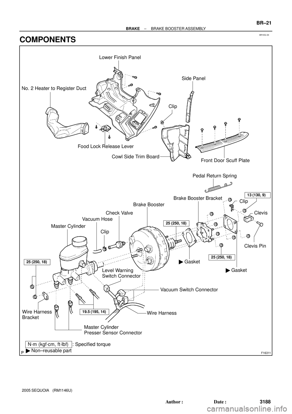
F16311
Master CylinderVacuum Hose
Level Warning
Switch ConnectorBrake Booster
� GasketClevis Pin Brake Booster Bracket Clip
: Specified torque
N´m (kgf´cm, ft´lbf)
� Non±reusable partPedal Return Spring
Wire Harness
Bracket
Lower Finish Panel
Food Lock Release Lever No. 2 Heater to Register Duct
Cowl Side Trim Board
Front Door Scuff Plate
� GasketClevis
Vacuum Switch Connector
19.5 (195, 14)
25 (250, 18)
25 (250, 18)
ClipCheck Valve
25 (250, 18)
Side Panel
Wire Harness
13 (130, 9)
Clip
Master Cylinder
Presser Sensor Connector
± BRAKEBRAKE BOOSTER ASSEMBLY
BR±21
3188 Author�: Date�:
2005 SEQUOIA (RM1146U)
COMPONENTS
Page 3229 of 4323
BR1NL±04
BR±54
± BRAKEABS & VSC ACTUATOR
3221 Author�: Date�:
2005 SEQUOIA (RM1146U)
INSTALLATION
Installation is in the reverse order of removal (See page BR±51).
HINT:
�After installation, fill the brake reservoir with brake fluid and bleed brake system (See page BR±4).
�Check for leaks.
NOTICE:
In case of replacing the skid control ECU, perform the zero point calibration of the steering angle,
master cylinder pressure, yawrate and deceleration sensors (See page DI±897).
Page 3230 of 4323
BR0A2±05
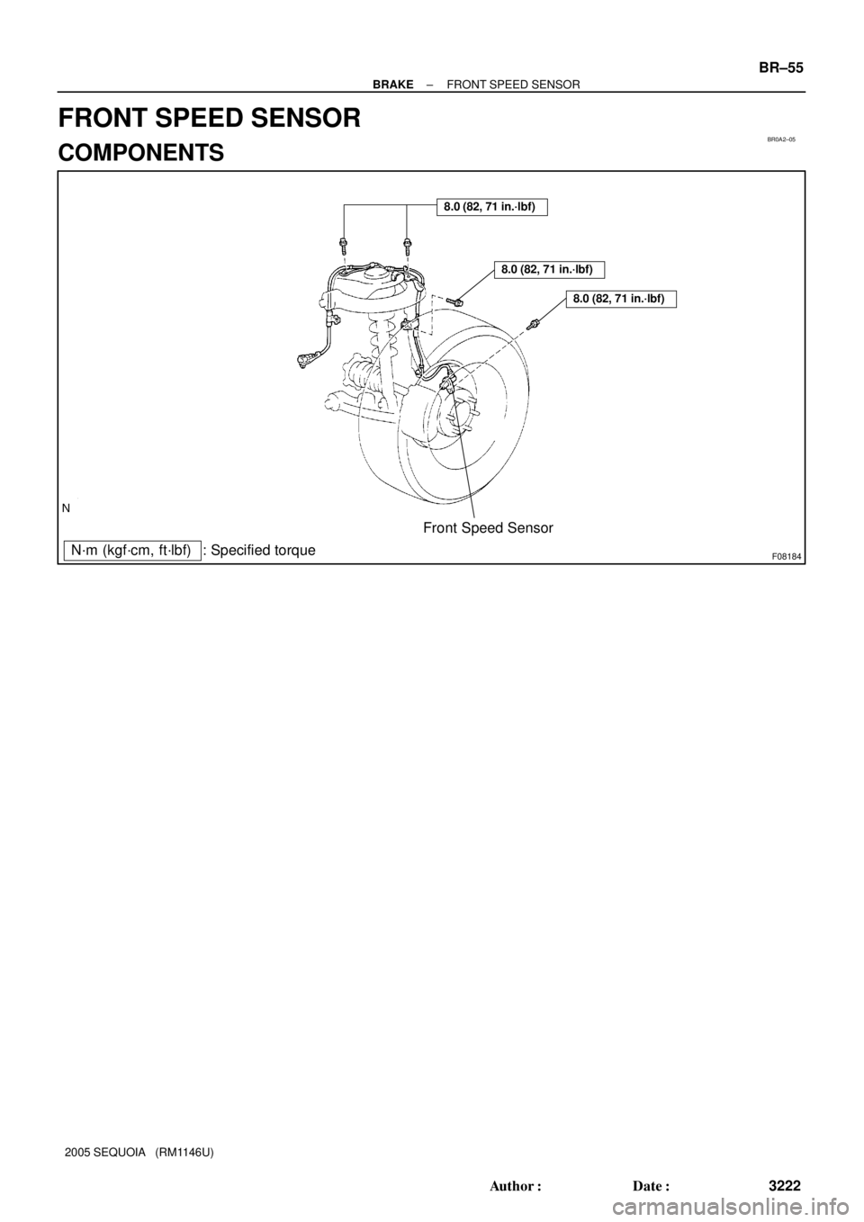
F08184
8.0 (82, 71 in.´lbf)
8.0 (82, 71 in.´lbf)
Front Speed Sensor
: Specified torque
N´m (kgf´cm, ft´lbf)
8.0 (82, 71 in.´lbf)
± BRAKEFRONT SPEED SENSOR
BR±55
3222 Author�: Date�:
2005 SEQUOIA (RM1146U)
FRONT SPEED SENSOR
COMPONENTS
Page 3231 of 4323
BR0A3±04
F08186
BR±56
± BRAKEFRONT SPEED SENSOR
3223 Author�: Date�:
2005 SEQUOIA (RM1146U)
REMOVAL
1. REMOVE FRONT WHEEL
Torque: 110 N´m (1,122 kgf´cm, 81 ft´lbf)
2. DISCONNECT SPEED SENSOR CONNECTOR
3. REMOVE SPEED SENSOR
(a) Remove the clips and 3 clamp bolts holding the sensor
harness from the frame, upper arm and steering knuckle.
Torque: 8.0 N´m (82 kgf´cm, 71 in.´lbf)
(b) Remove the bolt and speed sensor from the steering
knuckle.
Torque: 8.0 N´m (82 kgf´cm, 71 in.´lbf)
Page 3232 of 4323
BR0A4±07
± BRAKEFRONT SPEED SENSOR
BR±57
3224 Author�: Date�:
2005 SEQUOIA (RM1146U)
INSTALLATION
Installation is in the reverse order of removal (See page BR±56).
HINT:
After installation, check speed sensor signal (See page DI±899).
Page 3233 of 4323
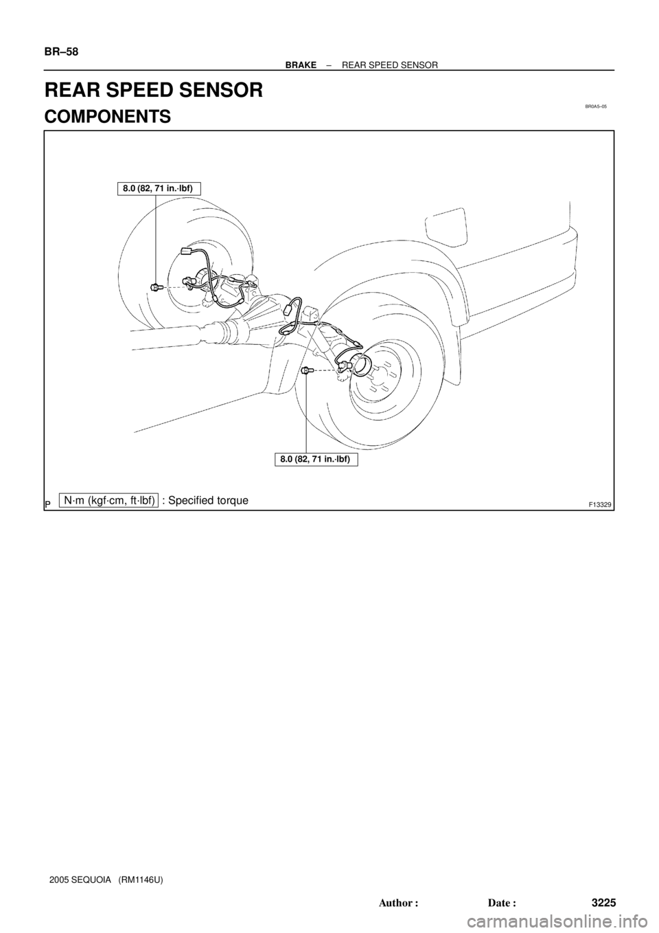
BR0A5±05
F13329N´m (kgf´cm, ft´lbf) : Specified torque
8.0 (82, 71 in.´lbf)
8.0 (82, 71 in.´lbf)
BR±58
± BRAKEREAR SPEED SENSOR
3225 Author�: Date�:
2005 SEQUOIA (RM1146U)
REAR SPEED SENSOR
COMPONENTS
Page 3234 of 4323
BR0A6±04
F13328
± BRAKEREAR SPEED SENSOR
BR±59
3226 Author�: Date�:
2005 SEQUOIA (RM1146U)
REMOVAL
1. DISCONNECT SPEED SENSOR CONNECTOR
2. REMOVE SPEED SENSOR
(a) Remove the 6 resin clips holding the sensor wire harness.
(b) Remove the bolt and speed sensor from the axle carrier.
Torque: 8.0 N´m (82 kgf´cm, 71 in.´lbf)
Page 3235 of 4323
BR0A7±07
BR±60
± BRAKEREAR SPEED SENSOR
3227 Author�: Date�:
2005 SEQUOIA (RM1146U)
INSTALLATION
Installation is in the reverse order of removal (See page BR±59).
HINT:
After installation, check speed sensor signal (See page DI±899).