Page 2820 of 4323
SF1UM±05
B16380
Accelerator Pedal
Assembly
N´m (kgf´cm, ft´lbf) : Specified torqueAccelerator Pedal
Position Sensor
Accelerator Pedal Position
Sensor Connector
5.0 (51, 44 in.´lbf)
SF±78
± SFIACCELERATOR PEDAL POSITION SENSOR
2812 Author�: Date�:
2005 SEQUOIA (RM1146U)
ACCELERATOR PEDAL POSITION SENSOR
COMPONENTS
Page 2821 of 4323
SF1UN±02
± SFIACCELERATOR PEDAL POSITION SENSOR
SF±79
2813 Author�: Date�:
2005 SEQUOIA (RM1146U)
INSPECTION
INSPECT ACCELERATOR PEDAL POSITION SENSOR (See page DI±370)
If necessary, replace the accelerator pedal assembly.
NOTICE:
�Be care not to give a shock to the accelerator pedal assembly.
�Be care not to disassemble the accelerator pedal assembly.
Page 2828 of 4323
B17476
RH No.3 Timing Belt Cover
LH No.3 Timing Belt CoverNo.2 Timing Belt Cover
Camshaft Position
Sensor Connector
Engine Wire
Oil Cooler Pipe
Timing Belt
Fan Bracket Drive Belt Timing Pulley
Timing Belt Tensioner Dust Boot
N´m (kgf´cm, ft´lbf) : Specified torque Cover Plate
39 (400,29)
32 (330, 24)
16 (160, 12)
Water Bypass
Hose
Grommet
16 (160, 12)
245 (2,500, 181)
CO±4
± COOLINGWATER PUMP
2820 Author�: Date�:
2005 SEQUOIA (RM1146U)
Page 2829 of 4323
B17477
Generator Wire
Generator Connector
Generator
Crankshaft PulleyDrive Belt Tensioner
No.1 Timing Belt Cover
Timing Belt
Timing Belt Guide
(Crankshaft Angle Sensor Plate)No.2 Idler Pulley
Timing Belt Cover SpacerGasket
N´m (kgf´cm, ft´lbf) : Specified torque
� Non±reusable partWater Inlet Housing
Assembly
Water Pump � O±Ring
� Gasket � O±Ring
39 (400, 29)
18 (185, 13)
21 (215, 15)
Wire
Clamp
PS Vane Pump
(100 A Type Generator)
15.5 (158, 11)
39 (400, 29)
34.5 (350, 25)
± COOLINGWATER PUMP
CO±5
2821 Author�: Date�:
2005 SEQUOIA (RM1146U)
Page 2846 of 4323
LU08P±10
B17476
RH No.3 Timing Belt Cover
LH No.3 Timing Belt CoverNo.2 Timing Belt Cover
Camshaft Position
Sensor Connector
Engine Wire
Drive Belt Idler PulleyTiming Belt
Fan Bracket
N´m (kgf´cm, ft´lbf) : Specified torqueOil Cooler Pipe
Timing Belt Tensioner Dust Boot
Cover Plate
32 (330, 24)
Water Bypass
Hose
Grommet
245 (2,500, 181)
39 (400,29)
16 (160, 12)
16 (160, 12)
LU±4
± LUBRICATIONOIL PUMP
2838 Author�: Date�:
2005 SEQUOIA (RM1146U)
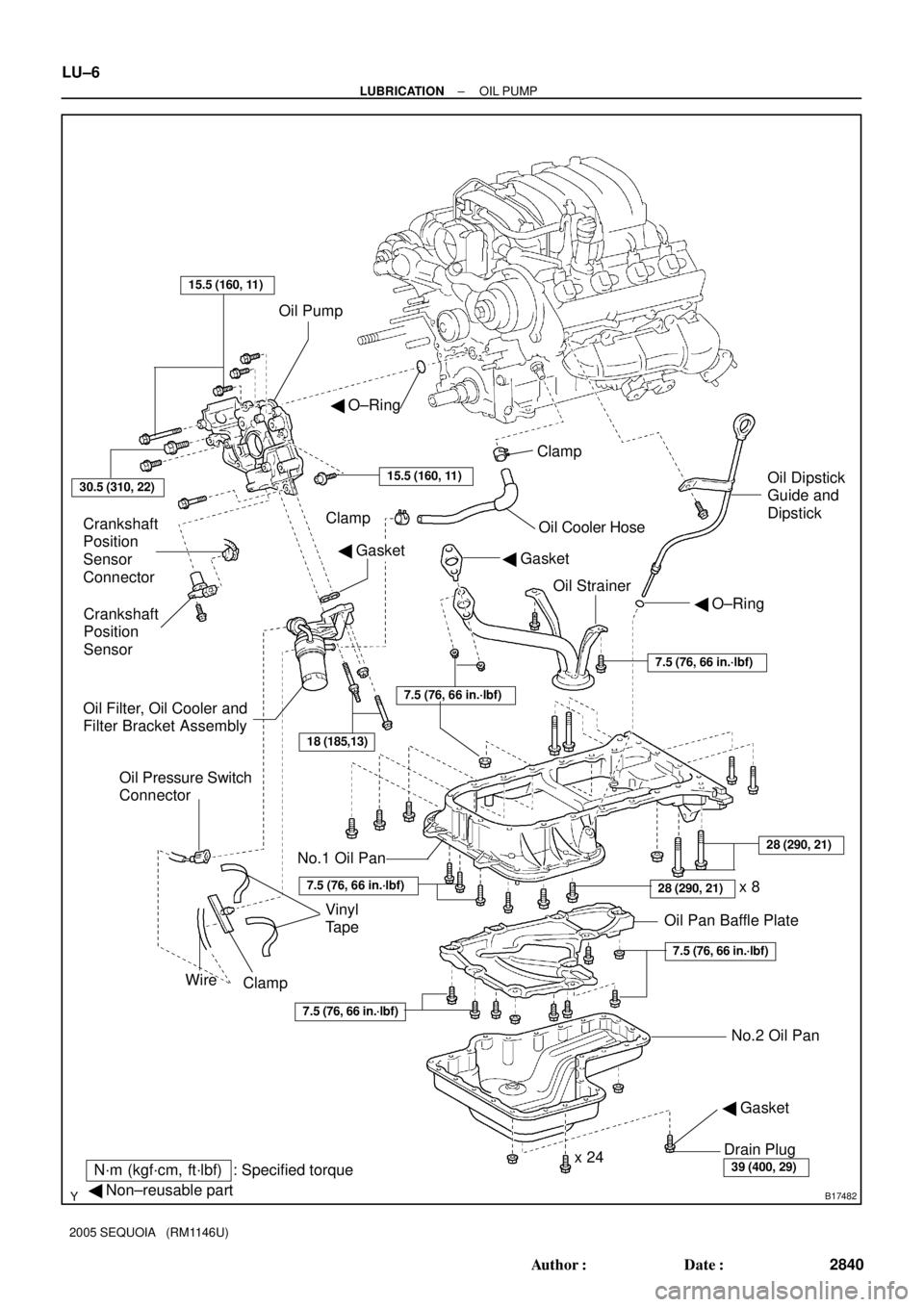
OIL PUMP
COMPONENTS
Page 2847 of 4323
B17481
GeneratorDrive Belt Tensioner
No.1 Timing Belt Cover
Crankshaft Pulley
Timing Belt
Timing Belt Guide
(Crankshaft Angle Sensor Plate)No.1 Idler Pulley
Crankshaft Timing PulleyPlate Washer
No.2 Idler Pulley
Timing Belt Cover SpacerGasket
� Precoated part
N´m (kgf´cm, ft´lbf) : Specified torque
39 (400, 29)
Generator Wire
�34.5 (350, 25)
34.5 (350, 25)
39 (400, 29)
15.5 (158, 11)
± LUBRICATIONOIL PUMP
LU±5
2839 Author�: Date�:
2005 SEQUOIA (RM1146U)
Page 2848 of 4323
B17482
Oil Pump
Crankshaft
Position
Sensor
Connector
Crankshaft
Position
Sensor
Oil Filter, Oil Cooler and
Filter Bracket AssemblyOil Cooler Hose Clamp
Oil StrainerOil Dipstick
Guide and
Dipstick � O±Ring
� Gasket
No.1 Oil Pan
No.2 Oil Pan Oil Pan Baffle Plate Clamp
Drain Plug
x 24
N´m (kgf´cm, ft´lbf) : Specified torque
� Non±reusable part
� Gasket
30.5 (310, 22)
� O±Ring
15.5 (160, 11)
18 (185,13)
Vinyl
Tape
Wire
Clamp
Oil Pressure Switch
Connector
15.5 (160, 11)
� Gasket
39 (400, 29)
x 828 (290, 21)
7.5 (76, 66 in.´lbf)
28 (290, 21)
7.5 (76, 66 in.´lbf)
7.5 (76, 66 in.´lbf)
7.5 (76, 66 in.´lbf)
7.5 (76, 66 in.´lbf)
LU±6
± LUBRICATIONOIL PUMP
2840 Author�: Date�:
2005 SEQUOIA (RM1146U)
Page 2850 of 4323

REMOVAL
HINT:
When repairing the oil pump, the oil pan and strainer should be
removed an")
LU08Q±10
B05837
Pull O±Ring
B05838
LU±8
± LUBRICATIONOIL PUMP
2842 Author�: Date�:
2005 SEQUOIA (RM1146U)
REMOVAL
HINT:
When repairing the oil pump, the oil pan and strainer should be
removed and cleaned.
1. REMOVE ENGINE FROM VEHICLE
(2WD: See page EM±79)
(4WD: See page EM±92)
2. INSTALL ENGINE TO ENGINE STAND FOR DIS-
ASSEMBLY
3. REMOVE TIMING BELT (See page EM±16)
4. REMOVE NO.1 IDLER PULLEY (See page EM±16)
5. REMOVE NO.2 IDLER PULLEY (See page EM±16)
6. REMOVE CRANKSHAFT TIMING PULLEY
(See page EM±16)
7. REMOVE CRANKSHAFT POSITION SENSOR
(See page IG±11)
8. REMOVE OIL DIPSTICK AND GUIDE
(a) Remove the bolt holding the oil dipstick to the LH cylinder
head.
(b) Pull out the dipstick guide together with the dipstick from
the No.1 oil pan.
(c) Remove the O±ring from the dipstick guide.
9. REMOVE OIL FILTER, OIL COOLER AND FILTER
BRACKET ASSEMBLY
(a) Disconnect the oil pressure switch connector.
(b) Take out the vinyl tape, and disconnect the wire from the
clamp.
(c) Turn the clamp counterclockwise, and remove the clamp
from the oil filter bracket.
(d) Disconnect the oil cooler hose from the oil cooler.
(e) Remove the 2 bolts, nut, the oil filter, oil cooler and filter
bracket assembly.
(f) Remove the gasket from the filter bracket.
 : Specified torqueAccelerator Pedal
Position Sensor
Accelerator Pedal Position
Sensor Connector
5.0 (51, 44 in.´lbf)
SF±78
± SFIA")


No.2 Idler Pulley
Timing B")

No.1 Idler Pulley
Crankshaft Timing PulleyPlate Washer
No.2 I")