Page 2366 of 4323
I28203
I28204
I28187
Radio and Display Assy
Navigation ECURadio and Navigation Assy DI±2164
± DIAGNOSTICSNAVIGATION SYSTEM
2358 Author�: Date�:
2005 SEQUOIA (RM1146U)
(9) When the vehicle runs on the snowy road or a
mountain path with the chains installed or using a
spare tire, the current vehicle position mark may
deviate from the correct position.
(10) When a tire is changed, the current vehicle position
mark may deviate from the correct position.
HINT:
�Diameter of the tire may change, causing a speed sensor
error.
�Performing the ºtire changeº in calibration mode will allow
the system to correct the current vehicle position faster.
2. Radio and navigation assy outline
Conventionally, 2 separate devices, a ºradio and display assyº and a ºnavigation ECUº are used. This model
has adopted a new type, combining these devices into a single unit.
Page 2367 of 4323

I28188
GPS satellite
Navigation
Gyro Sensor
ECU GPS Antenna
Receive satellite
radio waveGPS correction
Create the current
vehicle position
tracking data
Navigation screen
Map disc Map matching
correction Detect direction
change Detect vehicle
running distance
Radio and Navigation Assy
Detect the
measurement position
Map scrolling
Map scale switching Map and current vehicle
position data processing Vehicle Speed Sensor
GPS Antenna
Vehicle Speed SensorLocation by
GPS navigation
Gyro Sensor
Location by
autonomous navigation
± DIAGNOSTICSNAVIGATION SYSTEM
DI±2165
2359 Author�: Date�:
2005 SEQUOIA (RM1146U)
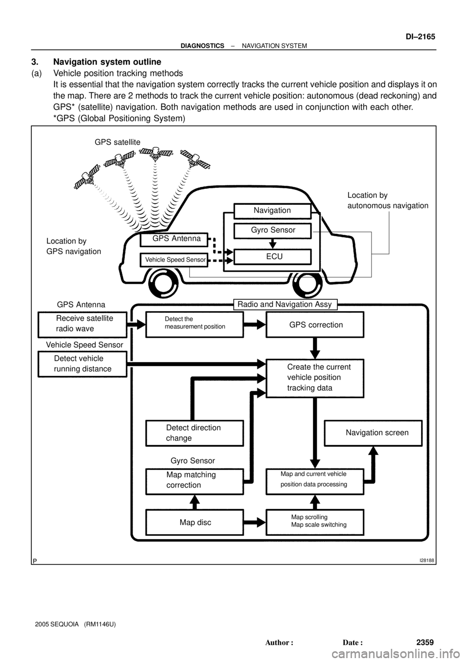
3. Navigation system outline
(a) Vehicle position tracking methods
It is essential that the navigation system correctly tracks the current vehicle position and displays it on
the map. There are 2 methods to track the current vehicle position: autonomous (dead reckoning) and
GPS* (satellite) navigation. Both navigation methods are used in conjunction with each other.
*GPS (Global Positioning System)
Page 2368 of 4323

I28189
Navigation performed even where the
GPS radio wave does not reach.
� In a tunnel
� In an indoor parking lot
� Between tall buildings
� Under an overpass
� On a forest or tree±lined path
Autonomous navigation
Autonomous navigation and
GPS navigationGPS satellite DI±2166
± DIAGNOSTICSNAVIGATION SYSTEM
2360 Author�: Date�:
2005 SEQUOIA (RM1146U)Operation
Description
Vehicle Position Calculation
The navigation ECU calculates the current vehicle position (direction and current
position) using the direction deviation signal from the gyro sensor and the running
distance signal from the vehicle speed sensor and creates the driving route.
Map Display processingThe navigation ECU displays the vehicle track on the map by processing the ve-
hicle position data, vehicle running track, and map data from the map disc.
Map MatchingThe map data from the map disc is compared to the vehicle position and running
track data. Then, the vehicle position is matched with the nearest road.
GPS Correction
The vehicle position is matched to the position measured by GPS. Then, the mea-
surement position data from the GPS unit is compared with the vehicle position and
running track data. If the position is widely different, the GPS measurement position
is used.
Distance Correction
The running distance signal from the vehicle speed sensor includes the error
caused by tire wear and slippage between the tires and road surface. Distance
correction is performed to account for this. The navigation ECU automatically off-
sets the running distance signal to make up for the difference between it and the
distance data of the map. The offset is automatically updated.
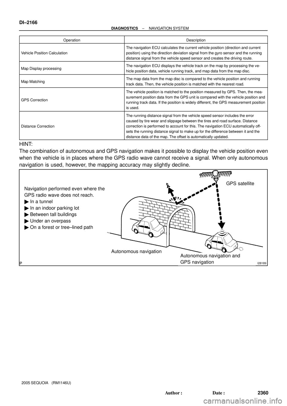
HINT:
The combination of autonomous and GPS navigation makes it possible to display the vehicle position even
when the vehicle is in places where the GPS radio wave cannot receive a signal. When only autonomous
navigation is used, however, the mapping accuracy may slightly decline.
Page 2369 of 4323

I28190
GPS Current longitude/latitude/altitude is determined using the radio wave arrival time from four satellites.
± DIAGNOSTICSNAVIGATION SYSTEM
DI±2167
2361 Author�: Date�:
2005 SEQUOIA (RM1146U)
(b) Autonomous navigation
This method determines the relative vehicle position based on the running track determined by the
gyro and vehicle speed sensors located in the navigation ECU.
(1) Gyro sensor
Calculates the direction by detecting angular velocity. It is located in the radio and navigation
assy.
(2) Vehicle speed sensor
Used to calculate the vehicle running distance.
(c) GPS navigation (Satellite navigation)
This method detects the absolute vehicle position using radio wave from a GPS satellite.
* GPS satellites were launched by the U.S. Department of Defence for military purposes.
Number of satellitesMeasurementDescription
2 or lessMeasurement impossibleVehicle position cannot be obtained because the number of satellites is not enough.
32±dimensional measure-
ment is possibleVehicle position is obtained based on the current longitude and latitude (This is less precise
than 3±dimensional measurement).
43±dimensional measure-
ment is possibleVehicle position is obtained based on the current longitude, latitude and altitude.
Page 2370 of 4323

I28191
AActual driving route
Driving route on the display
(Route by estimation)
Roads
The system compares the shape of the roads L1,
L2 and L3 to the estimated running track after the
vehicle makes a right turn. At point A, the vehicle
position differs enough from the shape of L1 that
the display switches to the road L2. Start
Map
Matching
I28192
Vy1
Vx1 Vx2
Vy2 Vx1 (Vy1)
Vx2 (Vy2)
Touch±sensitive switch positionThe touch switch detects the voltage ratio
and calculates the position on the screen. Glass
OuterInner
Contact DI±2168
± DIAGNOSTICSNAVIGATION SYSTEM
2362 Author�: Date�:
2005 SEQUOIA (RM1146U)
(d) Map matching
The current driving route is calculated by autonomous navigation (according to the gyro sensor and
vehicle speed sensor) and GPS navigation. This information is then compared with possible road
shapes from the map data in the map disc and the vehicle position is set onto the most appropriate
road.
(e) Touch switch
Touch switches are touch±sensitive (interactive) switches operated by touching the screen. When a
switch is pressed, the outer glass bends in to contact the inner glass at the pressed position. By doing
this, the voltage ratio is measured and the pressed position is detected.
Page 2383 of 4323
DIDC0±01
I28227
I28230
I28231
± DIAGNOSTICSNAVIGATION SYSTEM
DI±2181
2375 Author�: Date�:
2005 SEQUOIA (RM1146U)
NAVIGATION CHECK MODE (Vehicle Sensors)
HINT:
�This mode checks the vehicle signal status input to the radio and navigation assy.
�Illustrations may differ from the actual vehicle depending on the device settings and options. There-
fore, some detailed areas may not be shown exactly the same as on the actual vehicle.
1. Enter diagnostic mode (See page DI±2191).
2. Select ºNavigation Checkº from the ºDiagnosis
MENUº screen.
3. Select ºVehicle Sensorsº from the ºNavigation
Checkº screen.
4. Check all the signals and sensors when vehicle sig-
nal information is displayed.
HINT:
This screen is updated once per second when input signals to
the vehicle are changed.
Page 2399 of 4323

I28244
*1
*2
*3
I28245
*1
*2
*3
*4
± DIAGNOSTICSNAVIGATION SYSTEM
DI±2197
2391 Author�: Date�:
2005 SEQUOIA (RM1146U)
Position information/*4
DisplayContents
PositionLatitude and longitude information on the current position is displayed.
Date information/*5
DisplayContents
DateThe date/time information obtained from GPS signal is displayed in Greenwich
mean time (GMT). The last 4 digits are displayed.
(4) Vehicle Sensors Screen
Vehicle signal
DisplayContents
REV/*1REV signal ON/OFF state is displayed.
SPD/*2SPD signal condition is displayed.
Sensor signal
DisplayContents
Gyro sensor/*3Gyro sensor output condition is displayed (when the vehicle runs straight or is sta-
tionary, the voltage is approximately 2.5 V).
HINT:
Signals are updated once per second only when vehicle sensor signals are changed.
(5) Parts Information Screen
Screen description
DisplayContents
Navigation Manufacturer/*1Radio and navigation assy manufacturer is displayed.
Navigation Version No./*2Radio and navigation assy version is displayed.
Disc Manufacturer/*3Map disc manufacturer is displayed.
Disc Version No./*4Map disc version is displayed.
Page 2435 of 4323

± DIAGNOSTICSNAVIGATION SYSTEM
DI±2233
2427 Author�: Date�:
2005 SEQUOIA (RM1146U)
Abnormal noise occurs
INSPECTION PROCEDURE
1 Check speaker installation
CHECK:
Check if each speaker is securely installed.
OK:
Each speaker is securely installed.
HINT:
The radio is equipped with a noise prevention system that blocks only excessively loud noise. If loud noise
occurs, check that all wiring is proper and that the antenna installation part ground and noise±prevention
equipment are installed.
Conditions under which noise occursNoise type
Noise increases when the accelerator pedal is depressed, but stops when
the engine is stopped.Generator noise
Noise occurs during A/C or heater operation.Blower motor noise
Noise occurs when the vehicle accelerates rapidly on an unpaved road or
after the ignition switch is turned on.Fuel pump noise
Noise occurs when the horn switch is pressed and released or when pressed
and held.Horn noise
Quiet noise is occurs while the engine is running, but stops when the engine
is stopped.Ignition noise
Noise occurs synchronously with the blink of the turn signal.Flasher noise
Noise occurs during window washer operation.Washer noise
Noise occurs while the engine is running, and continues even after the engine
is stopped.Water temperature sensor noise
Noise occurs during wiper operation.Wiper noise
Noise occurs when the brake pedal is depressed.Stop light switch noise
Others.Static electricity stored on the vehicle
HINT:
�Identify the condition under which the noise occurs, and check the noise filter on the relevant part.
�First ensure that the noise is not coming from outside. Failure to do so makes noise source detection
difficult and may lead to a misdiagnosis.
�Noise should be removed in descending order of loudness.
NG Install it properly.
OK
Identification of noise source (See page DI±2174).
DIDCO±01