Page 2441 of 4323
I28260
I28261
± DIAGNOSTICSNAVIGATION SYSTEM
DI±2239
2433 Author�: Date�:
2005 SEQUOIA (RM1146U)
Vehicle position mark deviates greatly
INSPECTION PROCEDURE
1 Check GPS mark.
CHECK:
Check that the GPS mark is displayed.
OK:
The GPS mark is displayed.
NG Go to ºGPS mark is not displayedº in flow chart
(See page DI±2245).
OK
2 Navigation check mode (Vehicle sensors check).
PREPARATION:
Enter the ºNavigation Checkº mode (Vehicle Sensors) (See
page DI±2180).
CHECK:
While driving, compare the ºSPDº indicator to the reading on the
speedometer. Check that these readings are almost the same.
OK:
The readings are almost the same.
NG Go to ºspeed signal circuitº in flow chart
(See page DI±2291).
OK
DIDCW±01
Page 2442 of 4323
I28262
DI±2240
± DIAGNOSTICSNAVIGATION SYSTEM
2434 Author�: Date�:
2005 SEQUOIA (RM1146U)
3 Navigation check mode (Vehicle sensors check).
CHECK:
Check the ºREVº display according to the table below.
OK:
Shift leverDisplay
RON
Any position except ROFF
HINT:
The display is updated once per second. As a result, it is normal
for the display to lag behind the actual change in the switch.
NG Go to ºreverse signal circuitº in flow chart
(See page DI±2294).
OK
Proceed to next circuit inspection shown in problem symptoms table (See page DI±2184).
Page 2445 of 4323
I28261
± DIAGNOSTICSNAVIGATION SYSTEM
DI±2243
2437 Author�: Date�:
2005 SEQUOIA (RM1146U)
3 Navigation check mode (Vehicle sensors check).
PREPARATION:
Enter the ºNavigation Checkº mode (Vehicle Sensors) (See
page DI±2176).
CHECK:
While driving, compare the ºSPDº indicator to the reading on the
speedometer. Check if these readings are almost the same.
OK:
The readings are almost the same.
NG Go to ºspeed signal circuitº in flow chart
(See page DI±2291).
OK
Proceed to next circuit inspection shown in problem symptoms table (See page DI±2184).
Page 2455 of 4323
I28270
± DIAGNOSTICSNAVIGATION SYSTEM
DI±2253
2447 Author�: Date�:
2005 SEQUOIA (RM1146U)
Gyro error
INSPECTION PROCEDURE
1 Navigation check mode (Vehicle sensors check).
PREPARATION:
Enter the ºNavigation Checkº mode (Vehicle Sensors) (See
page DI±2180).
CHECK:
Check the gyro voltage.
OK:
0.1 to 4.5 V
NG Replace radio and navigation assy.
OK
Proceed to next circuit inspection shown in diagnostic trouble code chart (See page DI±2184).
DIDD6±01
Page 2457 of 4323
I28261
± DIAGNOSTICSNAVIGATION SYSTEM
DI±2255
2449 Author�: Date�:
2005 SEQUOIA (RM1146U)
Speed signal error
INSPECTION PROCEDURE
1 Navigation check mode (Vehicle sensors check).
CHECK:
(a) Enter the ºNavigation Checkº mode (Vehicle Sensors)
(See page DI±2180).
(b) While driving, compare the ºSPDº indicator to the reading
on the speedometer. Check if these readings are almost
the same.
OK:
The readings are almost the same.
OK Replace radio and navigation assy.
NG
Proceed to next circuit inspection shown in diagnostic trouble code chart (See page DI±2203).
DIDD9±01
Page 2462 of 4323
I28766
R6
Light Control
Rheostat AssyRadio and Navigation Assy
J/C
Steering Pad Switch Assy
Spiral Cable
Sub±assy From
TAILLIGHT
RelayILL±
SWG J/C
ILL+ W±G
GJ39 J40
J39 J40
J39 J40W±G
G
G
G A B
A
AAB
ILL±
T12
2
6 1
10C9±1
BR±W
C9±10 6
4
Steering SWR30
R27 R30 DI±2260
± DIAGNOSTICSNAVIGATION SYSTEM
2454 Author�: Date�:
2005 SEQUOIA (RM1146U)
Illumination circuit
CIRCUIT DESCRIPTION
Power is supplied to the radio and navigation panel illumination when the light control switch is in the TAIL
or HEAD position. The body ECU determines the external brightness based on the brightness level detected
by the automatic light control sensor, and then operates the TAILLIGHT relay. Power can also be supplied
by operating the relay.
The intensity of the radio receiver panel illumination can be adjusted by the rheostat switch.
WIRING DIAGRAM
DIDDF±01
Page 2494 of 4323

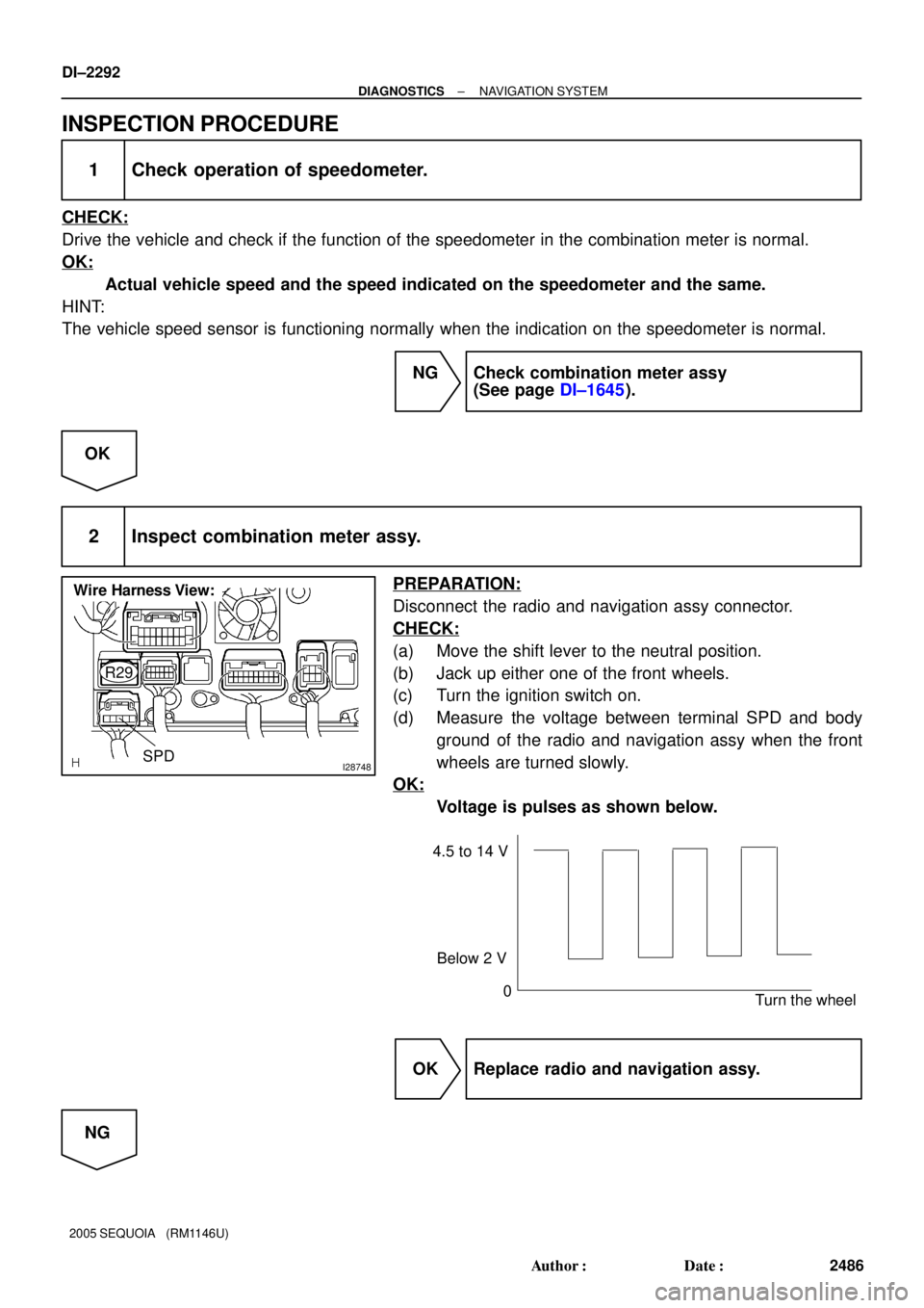
I28748SPD
Wire Harness View:
R29
4.5 to 14 V
0
Turn the wheel Below 2 V
DI±2292
± DIAGNOSTICSNAVIGATION SYSTEM
2486 Author�: Date�:
2005 SEQUOIA (RM1146U)
INSPECTION PROCEDURE
1 Check operation of speedometer.
CHECK:
Drive the vehicle and check if the function of the speedometer in the combination meter is normal.
OK:
Actual vehicle speed and the speed indicated on the speedometer and the same.
HINT:
The vehicle speed sensor is functioning normally when the indication on the speedometer is normal.
NG Check combination meter assy
(See page DI±1645).
OK
2 Inspect combination meter assy.
PREPARATION:
Disconnect the radio and navigation assy connector.
CHECK:
(a) Move the shift lever to the neutral position.
(b) Jack up either one of the front wheels.
(c) Turn the ignition switch on.
(d) Measure the voltage between terminal SPD and body
ground of the radio and navigation assy when the front
wheels are turned slowly.
OK:
Voltage is pulses as shown below.
OK Replace radio and navigation assy.
NG
Page 2501 of 4323
DIDKN±01
I28851
R/B No. 2
� Heater Main Relay
(Marking: HTR)
Compressor
Condenser
Receiver Pressure Switch
Integration Panel Assembly
� A/C ECU
� A/C Switch
� Air Inlet Selector
Heater Unit
� Heater Radiator
� Air Mix Servomotor
� Air Outlet Servomotor
Cooling Unit
� Blower Motor Linear
Controller
� Evaporator
� Expansion Valve
� ThermistorBlower Unit
� Blower Motor
� Air Inlet Servomotor
Water Valve
Rear Heater
Control Assembly
Condenser Fan
Ambient
Temperature
Sensor
Solar Sensor
Room
Temperature
Sensor
Rear Room Temperature
± DIAGNOSTICSAIR CONDITIONING SYSTEM
DI±2299
2493 Author�: Date�:
2005 SEQUOIA (RM1146U)
LOCATION