Page 1209 of 2572

05-1426
- DIAGNOSTICSSUPP")
H01002
H10600 C91338H91344H44128
Airbag
Sensor
Assy
CenterSpiral
Cable
Sub-assy
Color: Orange
DLC3
CG TCDTC B1182/19
Service WireD2-
D2+
FE
DC
D Squib
(Dual stage
- 2nd step)
05-1426
- DIAGNOSTICSSUPPLEMENTAL RESTRAINT SYSTEM
1616 Author�: Date�:
2005 HIGHLANDER REPAIR MANUAL (RM1144U)
2 CHECK AIR BAG SENSOR ASSY CENTER
(a) Connect the connector to the airbag sensor assy center.
(b) Using a service wire, connect D2+ and D2- of connector
ºEº.
NOTICE:
�Twist the end of the service wire in order to insert it
into the connector.
�Do not forcibly insert the twisted service wire into the
terminals of the connector when connecting.
(c) Connect the negative (-) terminal cable to the battery,
and wait for at least 2 seconds.
(d) Turn the ignition switch to the ON position, and wait for at
least 60 seconds.
(e) Clear the DTCs stored in memory (see page 05-1215).
(f) Turn the ignition switch to the LOCK position.
(g) Turn the ignition switch to the ON position, and wait for at
least 60 seconds.
(h) Check the DTCs (see page 05-1215).
OK:
DTC B1182/19 is not output.
HINT:
Codes other than code B1182/19 may be output at this time, but
they are not related to this check.
NG REPLACE AIR BAG SENSOR ASSY CENTER
(SEE PAGE 60-53)
OK
Page 1210 of 2572

FE
D
C
- DIAGNOSTICSSUPPLEMENTAL RESTRAINT SYSTEM
05-")
H01003H10600 C89253H01003H10600 C89253H42142
Airbag
Sensor
Assy
CenterSpiral
Cable
Sub-assy
DLC3
CG
TCDTC B1182/19
D Squib
(Dual stage
- 2nd step)
FE
D
C
- DIAGNOSTICSSUPPLEMENTAL RESTRAINT SYSTEM
05-1427
1617 Author�: Date�:
2005 HIGHLANDER REPAIR MANUAL (RM1144U)
3 CHECK HORN BUTTON ASSY(D SQUIB, DUAL STAGE - 2ND STEP)
(a) Turn the ignition switch to the LOCK position.
(b) Disconnect the negative (-) terminal cable from the bat-
tery, and wait for at least 90 seconds.
(c) Disconnect the service wire from connector ºEº.
(d) Connect the connectors to the horn button assy.
(e) Connect the negative (-) terminal cable to the battery,
and wait for at least 2 seconds.
(f) Turn the ignition switch to the ON position, and wait for at
least 60 seconds.
(g) Clear the DTCs stored in memory (see page 05-1215).
(h) Turn the ignition switch to the LOCK position.
(i) Turn the ignition switch to the ON position, and wait for at
least 60 seconds.
(j) Check the DTCs (see page 05-1215).
OK:
DTC B1182/19 is not output.
HINT:
Codes other than code B1182/19 may be output at this time, but
they are not related to this check.
NG REPLACE HORN BUTTON ASSY
(SEE PAGE 60-17)
OK
USE SIMULATION METHOD TO CHECK
HINT:
�Before performing the simulation method, check that the airbag sensor assy center is in check mode
(see page 05-1218).
�Perform the simulation method by selecting the check mode with the hand-held tester (see page
05-1218).
�After selecting the check mode, perform the simulation method by wiggling each connector of the air-
bag system or driving the vehicle on a city or rough road (see page 05-1218).
Page 1211 of 2572

A
FE
DC
BAirbag
Sensor
Assy
Center
Spiral
Cable
Sub-assy
D2+
Cowl Wire
D2-
A20
H01000
C91344H41441
Airbag
Sensor
Assy
CenterSpiral
Cable
Sub-assy
C")
H41440H41440H43066
D Squib
(Dual stage
- 2nd step)
A
FE
DC
BAirbag
Sensor
Assy
Center
Spiral
Cable
Sub-assy
D2+
Cowl Wire
D2-
A20
H01000
C91344H41441
Airbag
Sensor
Assy
CenterSpiral
Cable
Sub-assy
Color: Orange
D Squib
(Dual stage
- 2nd step)
A
FE
DC B
D2+D2-
Cowl Wire
05-1428
- DIAGNOSTICSSUPPLEMENTAL RESTRAINT SYSTEM
1618 Author�: Date�:
2005 HIGHLANDER REPAIR MANUAL (RM1144U)
4 CHECK COWL WIRE
(a) Disconnect the cowl wire connector from the spiral cable
sub-assy .
(b) Measure the resistance according to the value(s) in the
table below.
Standard:
Tester connectionConditionSpecified condition
A20-4 (D2+) -
Body groundAlways1 MW or Higher
A20-3 (D2-) -
Body groundAlways1 MW or Higher
NG REPAIR OR REPLACE COWL WIRE
OK
5 CHECK SPIRAL CABLE SUB-ASSY
(a) Measure the resistance according to the value(s) in the
table below.
Standard:
Tester connectionConditionSpecified condition
D2+ - Body groundAlways1 MW or Higher
D2- - Body groundAlways1 MW or Higher
NG REPAIR SPIRAL CABLE SUB-ASSY
(SEE PAGE 60-26)
OK
USE SIMULATION METHOD TO CHECK
HINT:
�Before performing the simulation method, check that the airbag sensor assy center is in check mode
(see page 05-1218).
�Perform the simulation method by selecting the check mode with the hand-held tester (see page
05-1218).
�After selecting the check mode, perform the simulation method by wiggling each connector of the air-
bag system or driving the vehicle on a city or rough road (see page 05-1218).
Page 1212 of 2572

FE
DC BA
D2+D2-
- DIAGNOSTICSSUPPLEMENTAL RESTRAINT SYSTEM
05-1429
1619 Author�: Dat")
H01001
C91344H41439
Airbag
Sensor
Assy
CenterSpiral
Cable
Sub-assy
Color: Orange
D Squib
(Dual stage
- 2nd step)
FE
DC BA
D2+D2-
- DIAGNOSTICSSUPPLEMENTAL RESTRAINT SYSTEM
05-1429
1619 Author�: Date�:
2005 HIGHLANDER REPAIR MANUAL (RM1144U)
DTC B1183/22 SHORT IN D SQUIB (DUAL STAGE - 2ND
STEP) CIRCUIT (TO B+)
CIRCUIT DESCRIPTION
The D squib (Dual stage - 2nd step) circuit consists of the airbag sensor assy center, the spiral cable sub-
assy and the horn button assy.
The circuit instructs the SRS to deploy when deployment conditions are met.
DTC B1183/22 is recorded when a short to B+ is detected in the D squib (Dual stage - 2nd step) circuit.
DTC No.DTC Detecting ConditionTrouble Area
B1183/22
�Short circuit in D squib (Dual stage - 2nd step) wire har-
ness (to B+)
�D squib (Dual stage - 2nd step) malfunction
�Spiral cable sub-assy malfunction
�Airbag sensor assy center malfunction�Horn button assy (D squib, Dual stage - 2nd step)
�Spiral cable sub-assy
�Airbag sensor assy center
�Cowl wire
WIRING DIAGRAM
see page 05-1416.
CIRCUIT INSPECTION
1 CHECK D SQUIB CIRCUIT(DUAL STAGE - 2ND STEP, AIRBAG SENSOR ASSY
CENTER - HORN BUTTON ASSY)
(a) Turn the ignition switch to the LOCK position.
(b) Disconnect the negative (-) terminal cable from the bat-
tery, and wait for at least 90 seconds.
(c) Disconnect the connectors from the airbag sensor assy
center and the horn button assy.
(d) Connect the negative (-) terminal cable to the battery,
and wait for at least 2 seconds.
(e) Turn the ignition switch to the ON position.
(f) Measure the voltage according to the value(s) in the table
below.
Standard:
Tester connectionConditionSpecified condition
D2+ - Body groundIgnition switch ONBelow 1 V
D2- - Body groundIgnition switch ONBelow 1 V
NG Go to step 4
OK
05IWH-01
Page 1213 of 2572

05-1430
- DIAGNOSTICSSUP")
H01002
H10600 C91342C891348H44129
Airbag
Sensor
Assy
CenterSpiral
Cable
Sub-assy
Color: Orange
DTC B1183/22
CGTC DLC3
Service Wire
D2-D2+
FE
DC
D Squib
(Dual stage
- 2nd step)
05-1430
- DIAGNOSTICSSUPPLEMENTAL RESTRAINT SYSTEM
1620 Author�: Date�:
2005 HIGHLANDER REPAIR MANUAL (RM1144U)
2 CHECK AIR BAG SENSOR ASSY CENTER
(a) Turn the ignition switch to the LOCK position.
(b) Disconnect the negative (-) terminal cable from the bat-
tery, and wait for at least 90 seconds.
(c) Connect the connector to the airbag sensor assy center.
(d) Using a service wire, connect D2+ and D2- of connector
ºEº.
NOTICE:
�Twist the end of the service wire in order to insert it
into the connector.
�Do not forcibly insert the twisted service wire into the
terminals of the connector when connecting.
(e) Connect the negative (-) terminal cable to the battery,
and wait for at least 2 seconds.
(f) Turn the ignition switch to the ON position, and wait for at
least 60 seconds.
(g) Clear the DTCs stored in memory (see page 05-1215).
(h) Turn the ignition switch to the LOCK position.
(i) Turn the ignition switch to the ON position, and wait for at
least 60 seconds.
(j) Check the DTCs (see page 05-1215).
OK:
DTC B1183/22 is not output.
HINT:
Codes other than code B1183/22 may be output at this time, but
they are not related to this check.
NG REPLACE AIR BAG SENSOR ASSY CENTER
(SEE PAGE 60-53)
OK
Page 1214 of 2572

FE
D
C
- DIAGNOSTICSSUPPLEMENTAL RESTRAINT SYSTEM
05-")
H01003H10600 C91342H01003H10600 C91342H42144
Airbag
Sensor
Assy
CenterSpiral
Cable
Sub-assy
DLC3
CG
TCDTC B1183/22
D Squib
(Dual stage
- 2nd step)
FE
D
C
- DIAGNOSTICSSUPPLEMENTAL RESTRAINT SYSTEM
05-1431
1621 Author�: Date�:
2005 HIGHLANDER REPAIR MANUAL (RM1144U)
3 CHECK HORN BUTTON ASSY(D SQUIB, DUAL STAGE - 2ND STEP)
(a) Turn the ignition switch to the LOCK position.
(b) Disconnect the negative (-) terminal cable from the bat-
tery, and wait for at least 90 seconds.
(c) Disconnect the service wire from connector ºEº.
(d) Connect the connectors to the horn button assy.
(e) Connect the negative (-) terminal cable to the battery,
and wait for at least 2 seconds.
(f) Turn the ignition switch to the ON position, and wait for at
least 60 seconds.
(g) Clear the DTCs stored in memory (see page 05-1215).
(h) Turn the ignition switch to the LOCK position.
(i) Turn the ignition switch to the ON position, and wait for at
least 60 seconds.
(j) Check the DTCs (see page 05-1215).
OK:
DTC B1183/22 is not output.
HINT:
Codes other than code B1183/22 may be output at this time, but
they are not related to this check.
NG REPLACE HORN BUTTON ASSY
(SEE PAGE 60-17)
OK
USE SIMULATION METHOD TO CHECK
HINT:
�Before performing the simulation method, check that the airbag sensor assy center is in check mode
(see page 05-1218).
�Perform the simulation method by selecting the check mode with the hand-held tester (see page
05-1218).
�After selecting the check mode, perform the simulation method by wiggling each connector of the air-
bag system or driving the vehicle on a city or rough road (see page 05-1218).
Page 1215 of 2572
H41440H41440H43066
Airbag
Sensor
Assy
CenterSpiral
Cable
Sub-assy
Cowl WireD Squib
(Dual stage
- 2nd step)
A
FE
DC
B
D2+
D2-
A20
05-1432
- DIAGNOSTICSSUPPLEMENTAL RESTRAINT SYSTEM
1622 Author�: Date�:
2005 HIGHLANDER REPAIR MANUAL (RM1144U)
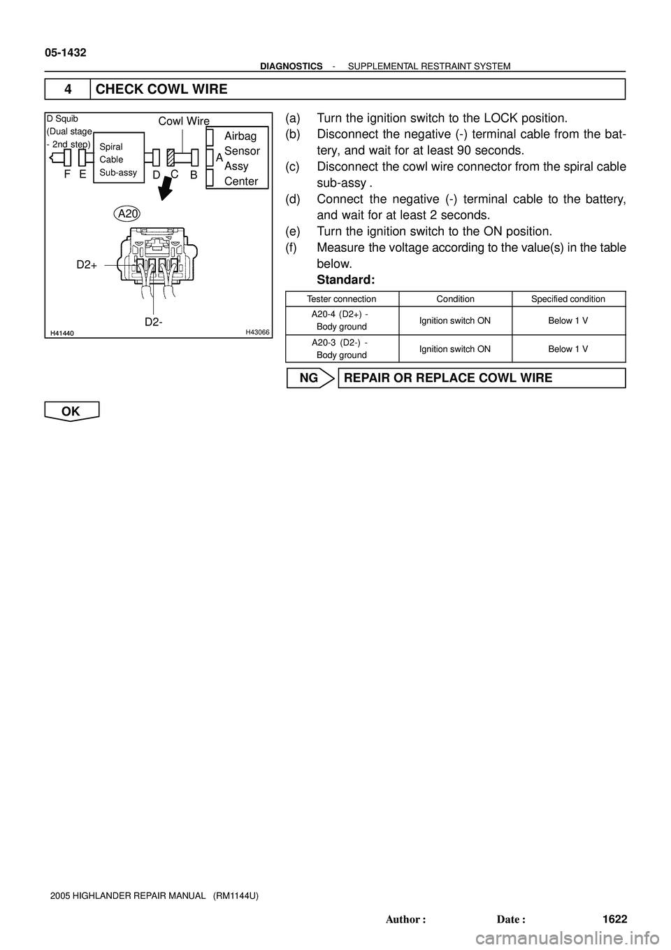
4 CHECK COWL WIRE
(a) Turn the ignition switch to the LOCK position.
(b) Disconnect the negative (-) terminal cable from the bat-
tery, and wait for at least 90 seconds.
(c) Disconnect the cowl wire connector from the spiral cable
sub-assy .
(d) Connect the negative (-) terminal cable to the battery,
and wait for at least 2 seconds.
(e) Turn the ignition switch to the ON position.
(f) Measure the voltage according to the value(s) in the table
below.
Standard:
Tester connectionConditionSpecified condition
A20-4 (D2+) -
Body groundIgnition switch ONBelow 1 V
A20-3 (D2-) -
Body groundIgnition switch ONBelow 1 V
NG REPAIR OR REPLACE COWL WIRE
OK
Page 1216 of 2572

A
FE
DC B
D2+D2-
Cowl Wire
- DIAGNOSTICSSUPPLEMENTAL RESTRAINT SYSTEM
05-1433
1623 Auth")
H01000
C91344H41441
Airbag
Sensor
Assy
CenterSpiral
Cable
Sub-assy
Color: Orange
D Squib
(Dual stage
- 2nd step)
A
FE
DC B
D2+D2-
Cowl Wire
- DIAGNOSTICSSUPPLEMENTAL RESTRAINT SYSTEM
05-1433
1623 Author�: Date�:
2005 HIGHLANDER REPAIR MANUAL (RM1144U)
5 CHECK SPIRAL CABLE SUB-ASSY
(a) Measure the voltage according to the value(s) in the table
below when the ignition switch remains in the ON posi-
tion.
Standard:
Tester connectionConditionSpecified condition
D2+ - Body groundIgnition switch ONBelow 1 V
D2- - Body groundIgnition switch ONBelow 1 V
NG REPLACE SPIRAL CABLE SUB-ASSY
(SEE PAGE 60-26)
OK
USE SIMULATION METHOD TO CHECK
HINT:
�Before performing the simulation method, check that the airbag sensor assy center is in check mode
(see page 05-1218).
�Perform the simulation method by selecting the check mode with the hand-held tester (see page
05-1218).
�After selecting the check mode, perform the simulation method by wiggling each connector of the air-
bag system or driving the vehicle on a city or rough road (see page 05-1218).