Page 1217 of 2572
H01454
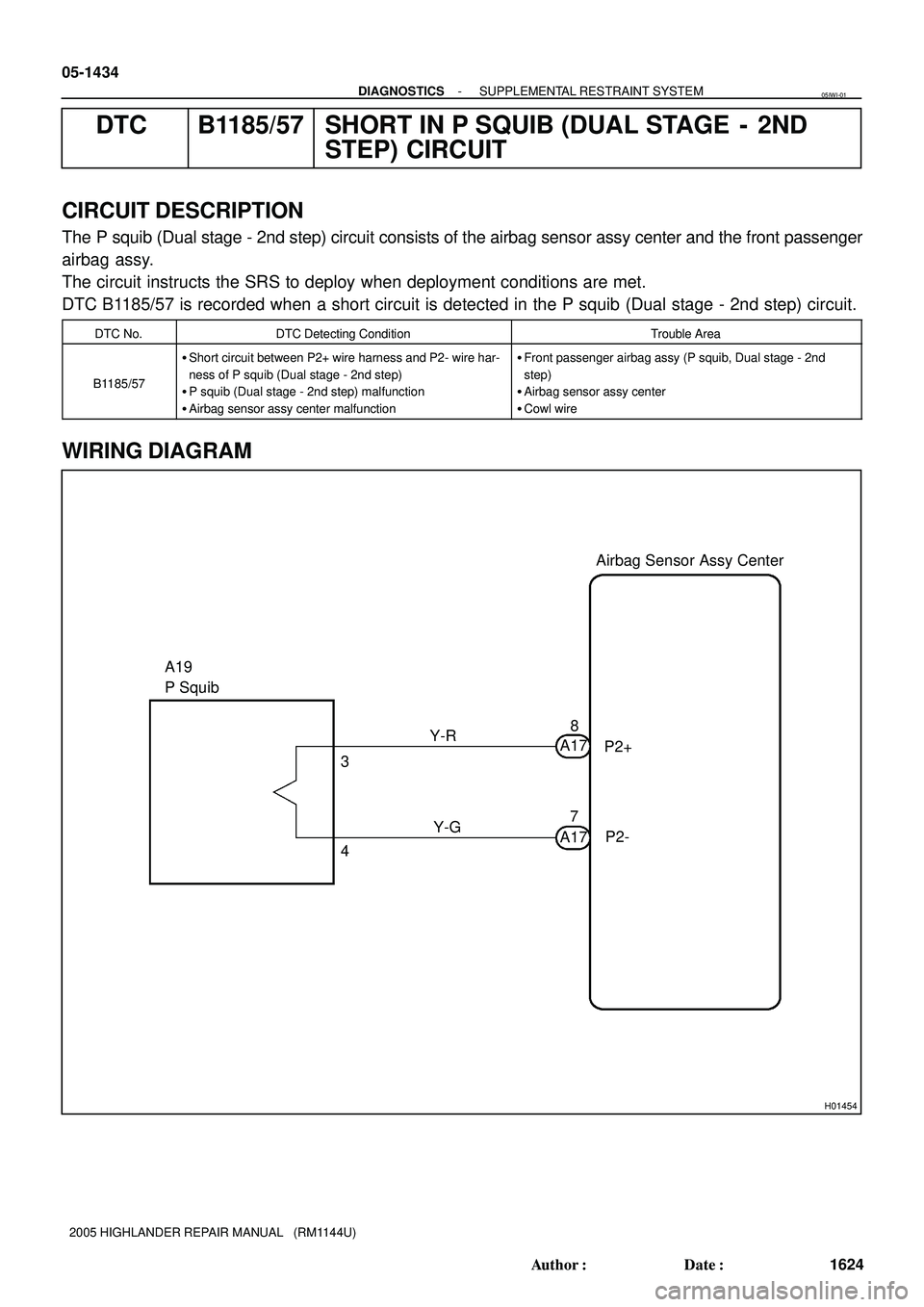
A19
P SquibAirbag Sensor Assy Center
Y-R
Y-G 3
48
P2+ A17
P2- 7
A17 05-1434
- DIAGNOSTICSSUPPLEMENTAL RESTRAINT SYSTEM
1624 Author�: Date�:
2005 HIGHLANDER REPAIR MANUAL (RM1144U)
DTC B1185/57 SHORT IN P SQUIB (DUAL STAGE - 2ND
STEP) CIRCUIT
CIRCUIT DESCRIPTION
The P squib (Dual stage - 2nd step) circuit consists of the airbag sensor assy center and the front passenger
airbag assy.
The circuit instructs the SRS to deploy when deployment conditions are met.
DTC B1185/57 is recorded when a short circuit is detected in the P squib (Dual stage - 2nd step) circuit.
DTC No.DTC Detecting ConditionTrouble Area
B1185/57
�Short circuit between P2+ wire harness and P2- wire har-
ness of P squib (Dual stage - 2nd step)
�P squib (Dual stage - 2nd step) malfunction
�Airbag sensor assy center malfunction�Front passenger airbag assy (P squib, Dual stage - 2nd
step)
�Airbag sensor assy center
�Cowl wire
WIRING DIAGRAM
05IWI-01
Page 1218 of 2572
Airbag
Sensor
Assy
Center
P2+ P2-Cowl Wire
A
B C
D
A19
H01023H10600H16840H01023H10600H16840H42145
P Squib
(Dual stage
- 2nd step)Airbag
Sensor
As")
R14286H41424H41932
P Squib
(Dual stage
- 2nd step)Airbag
Sensor
Assy
Center
P2+ P2-Cowl Wire
A
B C
D
A19
H01023H10600H16840H01023H10600H16840H42145
P Squib
(Dual stage
- 2nd step)Airbag
Sensor
Assy
Center
DLC3
CG TCDTC B1185/57
DC
- DIAGNOSTICSSUPPLEMENTAL RESTRAINT SYSTEM
05-1435
1625 Author�: Date�:
2005 HIGHLANDER REPAIR MANUAL (RM1144U)
INSPECTION PROCEDURE
1 CHECK COWL WIRE(P SQUIB, DUAL STAGE - 2ND STEP CIRCUIT)
(a) Turn the ignition switch to the LOCK position.
(b) Disconnect the negative (-) terminal cable from the bat-
tery, and wait for at least 90 seconds.
(c) Disconnect the connectors from the airbag sensor assy
center and the front passenger airbag assy.
(d) Release the activation prevention mechanism built into
connector ºBº (see page 05-1207).
(e) Measure the resistance according to the value(s) in the
table below.
Standard:
Tester connectionConditionSpecified condition
A19-3 (P2+) -
A19-4 (P2-)Always1 MW or Higher
NG REPAIR OR REPLACE COWL WIRE
OK
2 CHECK AIR BAG SENSOR ASSY CENTER
(a) Connect the connector to the airbag sensor assy center.
(b) Connect the negative (-) terminal cable to the battery,
and wait for at least 2 seconds.
(c) Turn the ignition switch to the ON position, and wait for at
least 60 seconds.
(d) Clear the DTCs stored in memory (see page 05-1215).
(e) Turn the ignition switch to the LOCK position.
(f) Turn the ignition switch to the ON position, and wait for at
least 60 seconds.
(g) Check the DTCs (see page 05-1215).
OK:
DTC B1185/57 is not output.
HINT:
Codes other than code B1185/57 may be output at this time, but
they are not related to this check.
NG REPLACE AIR BAG SENSOR ASSY CENTER
(SEE PAGE 60-53)
OK
Page 1219 of 2572
Airbag
Sensor
Assy
Center
DTC B1185/57
TC
CG
DLC3DC
05-1436
- DIAGNOSTICSSUPPLEMENTAL RESTRAINT SYSTEM
1626 Author�: Date�:
2")
H10600H01024H16840H10600H01024H16840H42146
P Squib
(Dual stage
- 2nd step)Airbag
Sensor
Assy
Center
DTC B1185/57
TC
CG
DLC3DC
05-1436
- DIAGNOSTICSSUPPLEMENTAL RESTRAINT SYSTEM
1626 Author�: Date�:
2005 HIGHLANDER REPAIR MANUAL (RM1144U)
3 CHECK FRONT PASSENGER AIRBAG ASSY(P SQUIB, DUAL STAGE - 2ND STEP)
(a) Turn the ignition switch to the LOCK position.
(b) Disconnect the negative (-) terminal cable from the bat-
tery, and wait for at least 90 seconds.
(c) Connect the connector to the front passenger airbag
assy.
(d) Connect the negative (-) terminal cable to the battery,
and wait for at least 2 seconds.
(e) Turn the ignition switch to the ON position, and wait for at
least 60 seconds.
(f) Clear the DTCs stored in memory (see page 05-1215).
(g) Turn the ignition switch to the LOCK position.
(h) Turn the ignition switch to the ON position, and wait for at
least 60 seconds.
(i) Check the DTCs (see page 05-1215).
OK:
DTC B1185/57 is not output.
HINT:
Codes other than code B1185/57 may be output at this time, but
they are not related to this check.
NG REPLACE FRONT PASSENGER AIRBAG ASSY
(SEE PAGE 60-29)
OK
USE SIMULATION METHOD TO CHECK
HINT:
�Before performing the simulation method, check that the airbag sensor assy center is in check mode
(see page 05-1218).
�Perform the simulation method by selecting the check mode with the hand-held tester (see page
05-1218).
�After selecting the check mode, perform the simulation method by wiggling each connector of the air-
bag system or driving the vehicle on a city or rough road (see page 05-1218).
Page 1220 of 2572
Airbag
Sensor
Assy
Center
P2+ P2-Cowl Wire
A
B C
D
A19
- DIAGNOSTICSSUPPLEMENTAL RESTRAINT SYSTEM
05-1437
1627 Author�: Date�:
2005 HIGHLANDER REP")
R14286H41424H41932
P Squib
(Dual stage
- 2nd step)Airbag
Sensor
Assy
Center
P2+ P2-Cowl Wire
A
B C
D
A19
- DIAGNOSTICSSUPPLEMENTAL RESTRAINT SYSTEM
05-1437
1627 Author�: Date�:
2005 HIGHLANDER REPAIR MANUAL (RM1144U)
DTC B1186/58 OPEN IN P SQUIB (DUAL STAGE - 2ND
STEP) CIRCUIT
CIRCUIT DESCRIPTION
The P squib (Dual stage - 2nd step) circuit consists of the airbag sensor assy center and the front passenger
airbag assy.
The circuit instructs the SRS to deploy when deployment conditions are met.
DTC B1186/58 is recorded when an open circuit is detected in the P squib (Dual stage - 2nd step) circuit.
DTC No.DTC Detecting ConditionTrouble Area
B1186/58
�Open circuit in P2+ wire harness or P2- wire harness of P
squib (Dual stage - 2nd step)
�P squib (Dual stage - 2nd step) malfunction
�Airbag sensor assy center malfunction�Front passenger airbag assy (P squib, Dual stage - 2nd
step)
�Airbag sensor assy center
�Cowl wire
WIRING DIAGRAM
see page 05-1434.
INSPECTION PROCEDURE
1 CHECK COWL WIRE(P SQUIB, DUAL STAGE - 2ND STEP CIRCUIT)
(a) Turn the ignition switch to the LOCK position
(b) Disconnect the negative (-) terminal cable from the bat-
tery, and wait for at least 90 seconds.
(c) Disconnect the connectors from the airbag sensor assy
center and the front passenger airbag assy.
(d) Measure the resistance according to the value(s) in the
table below.
Standard:
Tester connectionConditionSpecified condition
A19-3 (P2+) -
A19-4 (P2-)AlwaysBelow 1 W
NG REPAIR OR REPLACE COWL WIRE
OK
05IWJ-01
Page 1221 of 2572

A19
05-1438
- DIAGNOSTICSSUPPLEMENTAL RESTRAINT SYSTEM
162")
H01023
H10600H16841H16853H41981
P2+
P2-
DLC3
TC CG
Cowl Wire
SST
C D
DTC B1186/58 Airbag
Sensor
Assy
Center
P Squib
(Dual stage
- 2nd step)
A19
05-1438
- DIAGNOSTICSSUPPLEMENTAL RESTRAINT SYSTEM
1628 Author�: Date�:
2005 HIGHLANDER REPAIR MANUAL (RM1144U)
2 CHECK AIR BAG SENSOR ASSY CENTER
(a) Connect the connector to the airbag sensor assy center.
(b) Using SST, connect A19-3 (P2+) and A19-4 (P2-) of
connector ºCº.
SST 09843-18040
(c) Connect the negative (-) terminal cable to the battery,
and wait for at least 2 seconds.
(d) Turn the ignition switch to the ON position, and wait for at
least 60 seconds.
(e) Clear the DTCs stored in memory (see page 05-1215).
(f) Turn the ignition switch to the LOCK position.
(g) Turn the ignition switch to the ON position, and wait for at
least 60 seconds.
(h) Check the DTCs (see page 05-1215).
OK:
DTC B1186/58 is not output.
HINT:
Codes other than code B1186/58 may be output at this time, but
they are not related to this check.
NG REPLACE AIR BAG SENSOR ASSY CENTER
(SEE PAGE 60-53)
OK
Page 1222 of 2572

DC
- DIAGNOSTICSSUPPLEMENTAL RESTRAINT SYSTEM
05-1439
1629 Author�: Date�")
H10600H01024
H16841H10600H01024
H16841H42148
DLC3Airbag
Sensor
Assy
Center
TC CGDTC B1186/58 P Squib
(Dual stage
- 2nd step)
DC
- DIAGNOSTICSSUPPLEMENTAL RESTRAINT SYSTEM
05-1439
1629 Author�: Date�:
2005 HIGHLANDER REPAIR MANUAL (RM1144U)
3 CHECK FRONT PASSENGER AIRBAG ASSY(P SQUIB, DUAL STAGE - 2ND STEP)
(a) Turn the ignition switch to the LOCK position.
(b) Disconnect the negative (-) terminal cable from the bat-
tery, and wait for at least 90 seconds.
(c) Disconnect the SST from connector ºCº.
(d) Connect the connector to the front passenger airbag
assy.
(e) Connect the negative (-) terminal cable to the battery,
and wait for at least 2 seconds.
(f) Turn the ignition switch to the ON position, and wait for at
least 60 seconds.
(g) Clear the DTCs stored in memory (see page 05-1215).
(h) Turn the ignition switch to the LOCK position.
(i) Turn the ignition switch to the ON position, and wait for at
least 60 seconds.
(j) Check the DTCs (see page 05-1215).
OK:
DTC B1186/58 is not output.
HINT:
Codes other than code B1186/58 may be output at this time, but
they are not related to this check.
NG REPLACE FRONT PASSENGER AIRBAG ASSY
(SEE PAGE 60-29)
OK
USE SIMULATION METHOD TO CHECK
HINT:
�Before performing the simulation method, check that the airbag sensor assy center is in check mode
(see page 05-1218).
�Perform the simulation method by selecting the check mode with the hand-held tester (see page
05-1218).
�After selecting the check mode, perform the simulation method by wiggling each connector of the air-
bag system or driving the vehicle on a city or rough road (see page 05-1218).
Page 1223 of 2572
Airbag
Sensor
Assy
Center
P2+ Cowl Wire
A
B
C D
P2-
A19
05-1440
- DIAGNOSTICSSUPPLEMENTAL RESTRAINT SYSTEM
1630 Author�: Date�:
2005 HIGHLANDER RE")
R14286H41424H41932
P Squib
(Dual stage
- 2nd step)Airbag
Sensor
Assy
Center
P2+ Cowl Wire
A
B
C D
P2-
A19
05-1440
- DIAGNOSTICSSUPPLEMENTAL RESTRAINT SYSTEM
1630 Author�: Date�:
2005 HIGHLANDER REPAIR MANUAL (RM1144U)
DTC B1187/55 SHORT IN P SQUIB (DUAL STAGE - 2ND
STEP) CIRCUIT (TO GROUND)
CIRCUIT DESCRIPTION
The P squib (Dual stage - 2nd step) circuit consists of the airbag sensor assy center and the front passenger
airbag assy.
The circuit instructs the SRS to deploy when deployment conditions are met.
DTC B1187/55 is recorded when a short to ground is detected in the P squib (Dual stage - 2nd step) circuit.
DTC No.DTC Detecting ConditionTrouble Area
B1187/55
�Short circuit in P squib (Dual stage - 2nd step) wire har-
ness (to ground)
�P squib (Dual stage - 2nd step) malfunction
�Airbag sensor assy center malfunction�Front passenger airbag assy (P squib, Dual stage - 2nd
step)
�Airbag sensor assy center
�Cowl wire
WIRING DIAGRAM
see page 05-1434.
INSPECTION PROCEDURE
1 CHECK COWL WIRE(P SQUIB, DUAL STAGE - 2ND STEP CIRCUIT)
(a) Turn the ignition switch to the LOCK position.
(b) Disconnect the negative (-) terminal cable from the bat-
tery, and wait for at least 90 seconds.
(c) Disconnect the connectors from the airbag sensor assy
center and the front passenger airbag assy.
(d) Measure the resistance according to the value(s) in the
table below.
Standard:
Tester connectionConditionSpecified condition
A19-3 (P2+) -
Body groundAlways1 MW or Higher
A19-4 (P2-) -
Body groundAlways1 MW or Higher
NG REPAIR OR REPLACE COWL WIRE
OK
05IWK-01
Page 1224 of 2572
Cowl Wire
C
D
A19
SST
- DIAGNOSTICSSUPPLEMENTAL RESTRAINT SYSTEM
05-1441
1631 Au")
H01023
H10600H16838H16853H41983
Airbag
Sensor
Assy
Center
P2+
P2-
DLC3DTC B1187/55
TC CG
P Squib
(Dual stage
- 2nd step)Cowl Wire
C
D
A19
SST
- DIAGNOSTICSSUPPLEMENTAL RESTRAINT SYSTEM
05-1441
1631 Author�: Date�:
2005 HIGHLANDER REPAIR MANUAL (RM1144U)
2 CHECK AIR BAG SENSOR ASSY CENTER
(a) Connect the connector to the airbag sensor assy center.
(b) Using SST, connect A19-3 (P2+) and A19-4 (P2-) of
connector ºCº.
SST 09843-18040
(c) Connect the negative (-) terminal cable to the battery,
and wait for at least 2 seconds.
(d) Turn the ignition switch to the ON position, and wait for at
least 60 seconds.
(e) Clear the DTCs stored in memory (see page 05-1215).
(f) Turn the ignition switch to the LOCK position.
(g) Turn the ignition switch to the ON position, and wait for at
least 60 seconds.
(h) Check the DTCs (see page 05-1215).
OK:
DTC B1187/55 is not output.
HINT:
Codes other than code B1187/55 may be output at this time, but
they are not related to this check.
NG REPLACE AIR BAG SENSOR ASSY CENTER
(SEE PAGE 60-53)
OK