Page 1225 of 2572

CGD
C
05-1442
- DIAGNOSTICSSUPPLEMENTAL RESTRAINT SYSTEM
1632 Author�: Date�:")
H10600H01024
H16838H10600H01024
H16838H42150
DTC B1187/55 DLC3Airbag
Sensor
Assy
Center
TC
P Squib
(Dual stage
- 2nd step)
CGD
C
05-1442
- DIAGNOSTICSSUPPLEMENTAL RESTRAINT SYSTEM
1632 Author�: Date�:
2005 HIGHLANDER REPAIR MANUAL (RM1144U)
3 CHECK FRONT PASSENGER AIRBAG ASSY(P SQUIB, DUAL STAGE - 2ND STEP)
(a) Turn the ignition switch to the LOCK position.
(b) Disconnect the negative (-) terminal cable from the bat-
tery, and wait for at least 90 seconds.
(c) Disconnect the SST from connector ºCº.
(d) Connect the connector to the front passenger airbag
assy.
(e) Connect the negative (-) terminal cable to the battery,
and wait for at least 2 seconds.
(f) Turn the ignition switch to the ON position, and wait for at
least 60 seconds.
(g) Clear the DTCs stored in memory (see page 05-1215).
(h) Turn the ignition switch to the LOCK position.
(i) Turn the ignition switch to the ON position, and wait for at
least 60 seconds.
(j) Check the DTCs (see page 05-1215).
OK:
DTC B1187/55 is not output.
HINT:
Codes other than code B1187/55 may be output at this time, but
they are not related to this check.
NG REPLACE FRONT PASSENGER AIRBAG ASSY
(SEE PAGE 05-1215)
OK
USE SIMULATION METHOD TO CHECK
HINT:
�Before performing the simulation method, check that the airbag sensor assy center is in check mode
(see page 05-1218).
�Perform the simulation method by selecting the check mode with the hand-held tester (see page
05-1218).
�After selecting the check mode, perform the simulation method by wiggling each connector of the air-
bag system or driving the vehicle on a city or rough road (see page 05-1218).
Page 1226 of 2572
Airbag
Sensor
Assy
Center
P2+ Cowl Wire
A
B C
D
P2-
A19
- DIAGNOSTICSSUPPLEMENTAL RESTRAINT SYSTEM
05-1443
1633 Author�: Date�:
2005 HIGHLANDER RE")
R14286H41424H41932
P Squib
(Dual stage
- 2nd step)Airbag
Sensor
Assy
Center
P2+ Cowl Wire
A
B C
D
P2-
A19
- DIAGNOSTICSSUPPLEMENTAL RESTRAINT SYSTEM
05-1443
1633 Author�: Date�:
2005 HIGHLANDER REPAIR MANUAL (RM1144U)
DTC B1188/56 SHORT IN P SQUIB (DUAL STAGE - 2ND
STEP) CIRCUIT (TO B+)
CIRCUIT DESCRIPTION
The P squib (Dual stage - 2nd step) circuit consists of the airbag sensor assy center and the front passenger
airbag assy.
The circuit instructs the SRS to deploy when deployment conditions are met.
DTC B1188/56 is recorded when a short to B+ is detected in the P squib (Dual stage - 2nd step) circuit.
DTC No.DTC Detecting ConditionTrouble Area
B1188/56
�Short circuit in P squib (Dual stage - 2nd step) wire har-
ness (to B+)
�P squib (Dual stage - 2nd step) malfunction
�Airbag sensor assy center malfunction�Front passenger airbag assy (P squib, Dual stage - 2nd
step)
�Airbag sensor assy center
�Cowl wire
WIRING DIAGRAM
see page 05-1434.
INSPECTION PROCEDURE
1 CHECK COWL WIRE(P SQUIB, DUAL STAGE - 2ND STEP CIRCUIT)
(a) Turn the ignition switch to the LOCK position.
(b) Disconnect the negative (-) terminal cable from the bat-
tery, and wait for at least 90 seconds.
(c) Disconnect the connectors from the airbag sensor assy
center and the front passenger airbag assy.
(d) Connect the negative (-) terminal cable to the battery,
and wait for at least 2 seconds.
(e) Turn the ignition switch to the ON position.
(f) Measure the voltage according to the value(s) in the table
below.
Standard:
Tester connectionConditionSpecified condition
A19-3 (P2+) -
Body groundIgnition switch ONBelow 1 V
A19-4 (P2-) -
Body groundIgnition switch ONBelow 1 V
NG REPAIR OR REPLACE COWL WIRE
OK
05IWM-01
Page 1227 of 2572
Cowl Wire
SST C
D
A19
05-1444
- DIAGNOSTICSSUPPLEMENTAL RESTRAINT SYSTEM
1634")
H01023
H10600H16839H16853H41985
Airbag
Sensor
Assy
Center
P2+
P2-
DTC B1188/56
DLC3
TC CG
P Squib
(Dual stage
- 2nd step)Cowl Wire
SST C
D
A19
05-1444
- DIAGNOSTICSSUPPLEMENTAL RESTRAINT SYSTEM
1634 Author�: Date�:
2005 HIGHLANDER REPAIR MANUAL (RM1144U)
2 CHECK AIR BAG SENSOR ASSY CENTER
(a) Turn the ignition switch to the LOCK position.
(b) Disconnect the negative (-) terminal cable from the bat-
tery, and wait for at least 90 seconds.
SST 09843-18040
(c) Connect the connector to the airbag sensor assy center.
(d) Using SST, connect A19-3 (P2+) and A19-4 (P2-) of
connector ºCº.
(e) Connect the negative (-) terminal cable to the battery,
and wait for at least 2 seconds.
(f) Turn the ignition switch to the ON position, and wait for at
least 60 seconds.
(g) Clear the DTCs stored in memory (see page 05-1215).
(h) Turn the ignition switch to the LOCK position.
(i) Turn the ignition switch to the ON position, and wait for at
least 60 seconds.
(j) Check the DTCs (see page 05-1215).
OK:
DTC B1188/56 is not output.
HINT:
Codes other than code B1188/56 may be output at this time, but
they are not related to this check.
NG REPLACE AIR BAG SENSOR ASSY CENTER
(SEE PAGE 60-53)
OK
Page 1228 of 2572

DC
- DIAGNOSTICSSUPPLEMENTAL RESTRAINT SYSTEM
05-1445
1635 Author�: Date�")
H10600 H01024H16839H10600
H01024H16839H42152
DTC B1188/56
DLC3Airbag
Sensor
Assy
Center
TC
CG
P Squib
(Dual stage
- 2nd step)
DC
- DIAGNOSTICSSUPPLEMENTAL RESTRAINT SYSTEM
05-1445
1635 Author�: Date�:
2005 HIGHLANDER REPAIR MANUAL (RM1144U)
3 CHECK FRONT PASSENGER AIRBAG ASSY(P SQUIB, DUAL STAGE - 2ND STEP)
(a) Turn the ignition switch to the LOCK position.
(b) Disconnect the negative (-) terminal cable from the bat-
tery, and wait for at least 90 seconds.
(c) Disconnect the SST from connector ºCº.
(d) Connect the connector to the front passenger airbag
assy.
(e) Connect the negative (-) terminal cable to the battery,
and wait for at least 2 seconds.
(f) Turn the ignition switch to the ON position, and wait for at
least 60 seconds.
(g) Clear the DTCs stored in memory (see page 05-1215).
(h) Turn the ignition switch to the LOCK position.
(i) Turn the ignition switch to the ON position, and wait for at
least 60 seconds.
(j) Check the DTCs (see page 05-1215).
OK:
DTC B1188/56 is not output.
HINT:
Codes other than code B1188/56 may be output at this time, but
they are not related to this check.
NG REPLACE FRONT PASSENGER AIRBAG ASSY
(SEE PAGE 60-29)
OK
USE SIMULATION METHOD TO CHECK
HINT:
�Before performing the simulation method, check that the airbag sensor assy center is in check mode
(see page 05-1218).
�Perform the simulation method by selecting the check mode with the hand-held tester (see page
05-1218).
�After selecting the check mode, perform the simulation method by wiggling each connector of the air-
bag system or driving the vehicle on a city or rough road (see page 05-1218).
Page 1230 of 2572
H45686
B9
Multiplex Network Body ECU
P5
Power Window
Regulator Master
Switch Assy
(Door ECU)
A17
Airbag Sensor
Assembly F7
FL Block
Assy2 1K
1A Y
1W-L
IB1IC3
810 1G
3 1D
2
2 L
9
CPUB
IB2 WD.C.C
5
IB2 V
BatteryMPX2
BDR10
GR
8
MPX2 2A
4F
5 BR
71
MPX27 V
SB
BR
Short
Connector
2W-B
IB1
W-B
4L
4L
W-B
IC GND
S30
222 Y5 IF3
IB2
7 1 61 2I
IL1ECU-B
4AO
8 8 BR Engine Room J/B
Passenger
Side J/B 4
FL Main W33
10 Instrument
Panel J/B
MPX1
Passenger
Side J/B BG
BR2 S31 FR
Door
ALT 05-2052
- DIAGNOSTICSMULTIPLEX COMMUNICATION SYSTEM
2242 Author�: Date�:
2005 HIGHLANDER REPAIR MANUAL (RM1144U)
WIRING DIAGRAM
Page 1231 of 2572
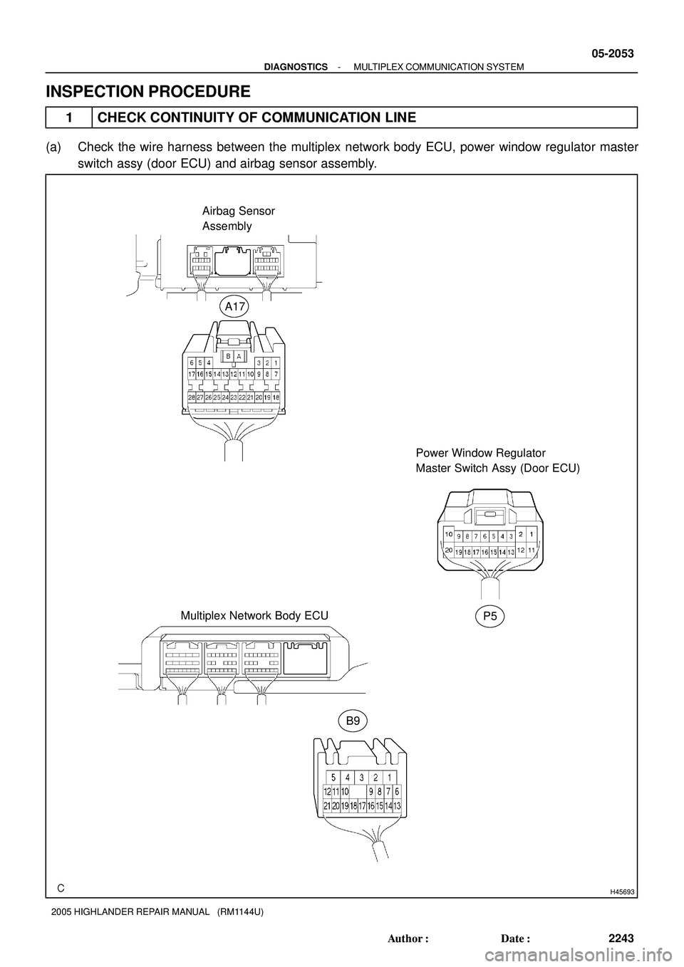
H45693
Power Window Regulator
Master Switch Assy (Door ECU)
Multiplex Network Body ECUAirbag Sensor
Assembly
A17
B9
P5
- DIAGNOSTICSMULTIPLEX COMMUNICATION SYSTEM
05-2053
2243 Author�: Date�:
2005 HIGHLANDER REPAIR MANUAL (RM1144U)
INSPECTION PROCEDURE
1 CHECK CONTINUITY OF COMMUNICATION LINE
(a) Check the wire harness between the multiplex network body ECU, power window regulator master
switch assy (door ECU) and airbag sensor assembly.
Page 1232 of 2572

(1) Disconnect the connectors of the master switch, body ECU and air condi")
B51827
P5
05-2054
- DIAGNOSTICSMULTIPLEX COMMUNICATION SYSTEM
2244 Author�: Date�:
2005 HIGHLANDER REPAIR MANUAL (RM1144U)
(1) Disconnect the connectors of the master switch, body ECU and air conditioner amplifier.
(2) Check the continuity between terminal P5-8 (MPX2) of the master switch vehicle's side connec-
tor and terminal B9-10 (MPX2) of the body ECU vehicle's side connector.
Standard: Continuity
(3) Check the continuity between terminal P5-7 (MPX1) of the master switch vehicle's side connec-
tor and terminal A17-22 (MPX2) of the airbag sensor assembly vehicle's side connector.
Standard: Continuity
NG REPAIR OR REPLACE HARNESS AND
CONNECTOR
OK
2 CHECK POWER WINDOW REGULATOR MASTER SWITCH ASSY
(a) Inspect the power window regulator master switch assy
(door ECU) (power source input).
(1) Disconnect the master switch connector.
(2) Check the voltage of each terminal of the master
switch vehicle's side connector.
Standard:
Symbols (Terminal No.)ConditionSpecified Condition
CPUB (P5-9) @ Body groundConstant10 - 14 V
BDR (P5-10) @ Body groundConstant10 - 14 V
NG REPAIR OR REPLACE FUSE OR WIRE
HARNESS AND CONNECTOR
OK
Page 1245 of 2572
B60591
P6
Power Window Regulator
Motor Assy Front LHP5
Power Window Regulator
Master Switch Assy (Door ECU)
2 6
315
5
13 PLS
LMTW
OPLS
LMT
R E
SGND
- DIAGNOSTICSPOWER WINDOW CONTROL SYSTEM
05-1913
2103 Author�: Date�:
2005 HIGHLANDER REPAIR MANUAL (RM1144U)
DTC B1231/31 JAM PROTECTION LIMIT SWITCH CIRCUIT
ON DRIVER DOOR
DTC B1232/32 JAM PROTECTION PULSE SWITCH CIRCUIT
ON DRIVER DOOR
CIRCUIT DESCRIPTION
This DTC is output when the power window regulator motor assy malfunctions.
DTC No.DTC Detecting ConditionTrouble Area
B1231/31Open in power window regulator motor assy LH limit switch
system�Power window regulator motor assy LH
�Wire harness
B1232/32Open or short in power window regulator motor assy LH
pulse sensor system�Power window regulator motor assy LH
�Wire harness
WIRING DIAGRAM
0523H-03

A17
Airbag Sensor
Assembly F7
FL Block
Assy2 1K
1A Y
1W-L
IB1IC3
810 1G
3 1D
2
2 L
9
CPUB
IB2 WD.C.C
5")

2 6
315
5
13 PLS
LMTW
OPLS
LMT
R E
SGND
- DIAGNOSTICSPOWER WINDOW CONTROL SYSTEM
05-1913
2")