Page 1269 of 2572
I41016
A1
E7
E6
1
2 Ambient Temperature Sensor
Connector Front View:
ECM Connector Wire Harness View:
ECM Connector Wire Harness View:
TA M E2
- DIAGNOSTICSAIR CONDITIONING SYSTEM
05-1 137
1327 Author�: Date�:
2005 HIGHLANDER REPAIR MANUAL (RM1144U)
NG REPLACE COOLER (AMBIENT TEMP. SENSOR)
THERMISTOR
OK
4 CHECK HARNESS AND CONNECTOR(COOLER (AMBIENT TEMPERATURE
SENSOR) THERMISTOR - ECM)
(a) Measure the resistance according to the value(s) in the
table below.
Standard:
Tester connectionConditionSpecified condition
E7-28 (E2) - A1-1AlwaysBelow 1 W
E6-32 (TAM) - A1-2AlwaysBelow 1 W
E7-28 (E2) -
Body groundAlways10 kW or higher
E6-32 (TAM) -
Body groundAlways10 kW or higher
NG REPAIR OR REPLACE HARNESS OR
CONNECTOR
OK
REPLACE ECM
Page 1270 of 2572
I30339
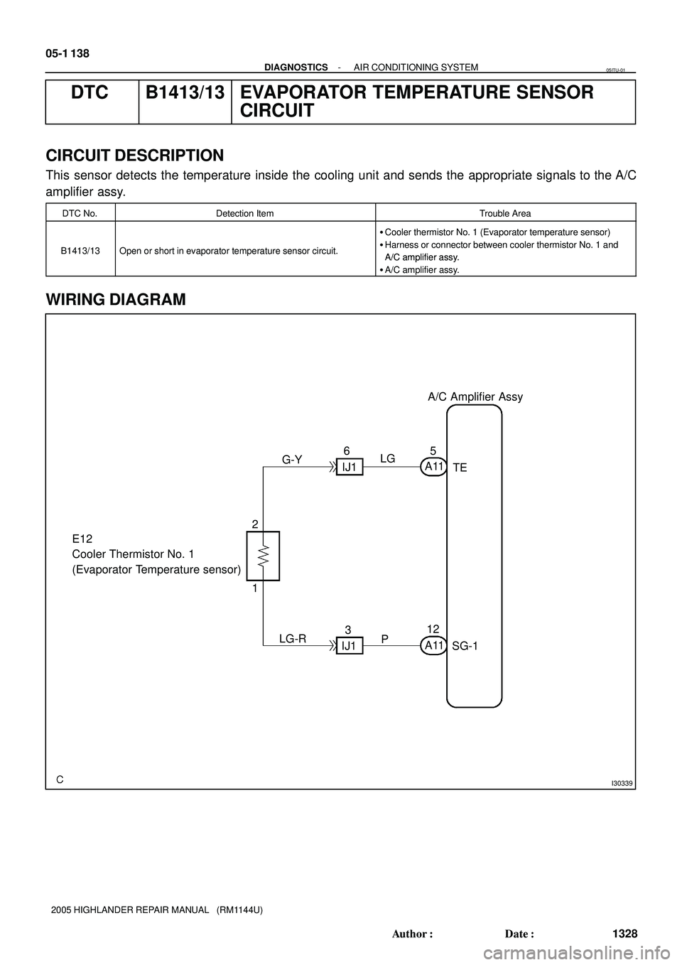
A/C Amplifier Assy
TE
SG-1 A115
12 LG
LG-R E12
Cooler Thermistor No. 1
(Evaporator Temperature sensor)
1 2G-Y6
IJ1
P
A11
IJ13 05-1 138
- DIAGNOSTICSAIR CONDITIONING SYSTEM
1328 Author�: Date�:
2005 HIGHLANDER REPAIR MANUAL (RM1144U)
DTC B1413/13 EVAPORATOR TEMPERATURE SENSOR
CIRCUIT
CIRCUIT DESCRIPTION
This sensor detects the temperature inside the cooling unit and sends the appropriate signals to the A/C
amplifier assy.
DTC No.Detection ItemTrouble Area
�Cooler thermistor No. 1 (Evaporator temperature sensor)
B1413/13Open or short in evaporator temperature sensor circuit.
()
�Harness or connector between cooler thermistor No. 1 and
A/C amplifier assyA/C amplifier assy.
�A/C amplifier assy.
WIRING DIAGRAM
05ITU-01
Page 1271 of 2572

SG-1 (-)
A11
A/C Amplifier Connector
Wire Harness View:
- DIAGNOSTICSAIR CONDITIONING SYSTEM
05-1 139
1329 Author�: Date�:
2005 HIGHLANDER REPAIR MANUAL (RM1144U)
INSPECTION PROCEDURE
H")
I30331TE (+)
SG-1 (-)
A11
A/C Amplifier Connector
Wire Harness View:
- DIAGNOSTICSAIR CONDITIONING SYSTEM
05-1 139
1329 Author�: Date�:
2005 HIGHLANDER REPAIR MANUAL (RM1144U)
INSPECTION PROCEDURE
HINT:
In case of using the hand-held tester, start the inspection step 1 and in case of not using the hand-held
tester, start from step 2.
1 READ VALUE OF HAND-HELD TESTER
(a) Connect the hand-held tester to DLC3.
(b) Turn the ignition switch ON and push the hand-held tester main switch ON.
(c) Select the items below in the DATA LIST, and read the displays on the hand-held tester.
A C:
ItemMeasurement Item/Display
(Range)Normal ConditionDiagnostic Note
EVAP TEMP
Evaporator temperature sensor
/min.: -29.7�C (-21.46�F)
max.: 59.55�C (139.19�F)
Actual evaporator temperature-
Result:
NGA
OK (Checking from the DTC)B
OK (Checking from the PROBLEM SYMPTOM TABLE)C
B REPLACE AIRCONDITIONER AMPLIFIER ASSY
C PROCEED TO NEXT CIRCUIT INSPECTION
SHOWN IN PROBLEM SYMPTOMS TABLE(SEE
PAGE 05-1 129)
A
2 INSPECT AIRCONDITIONER AMPLIFIER ASSY(TE, SG-1)
(a) Remove A/C amplifier assy with connectors still con-
nected.
(b) Turn the ignition switch to the ON position.
(c) Measure the voltage according to the value(s) in the table
below.
Standard:
Tester connectionConditionSpecified condition
A11-5 (TE) -
A11-12 (SG-1)at 0�C (32�F)2.0 to 2.4 V
A11-5 (TE) -
A11-12 (SG-1)at 15�C (59�F)1.4 to 1.8 V
OK REPLACE AIRCONDITIONER AMPLIFIER ASSY
NG
Page 1272 of 2572

Temperature -200
2040 (
5C)
3268
104 (
5F)
-4 2.04.0 5.0 7.08.0 10.0
Maximum permissible value lin")
E50650
E12
Cooler Thermistor
No.1 Connector
Front View:
I38756
9.0
6.0
3.0
0.0 1.0 Resistance
(kW)
Temperature -200
2040 (
5C)
3268
104 (
5F)
-4 2.04.0 5.0 7.08.0 10.0
Maximum permissible value line
Minimum permissible value line
05-1 140
- DIAGNOSTICSAIR CONDITIONING SYSTEM
1330 Author�: Date�:
2005 HIGHLANDER REPAIR MANUAL (RM1144U)
3 INSPECT COOLER THERMISTOR NO.1(EVAPORATOR TEMPERATURE SENSOR)
(a) Remove cooler thermistor No. 1.
(b) Check resistance between terminals 1 and 2 of cooler
thermistor No. 1 at each temperature, as shown in the
chart.
Standard:
Tester connectionConditionSpecified condition
E12-1 - E12-2-105C (145F)7.40 to 9.20 kW
E12-1 - E12-2-55C (235F)5.65 to 7.00 kW
E12-1 - E12-205C (325F)4.35 to 5.40 kW
E12-1 - E12-255C (415F)3.40 to 4.20 kW
E12-1 - E12-2105C (505F)2.68 to 3.30 kW
E12-1 - E12-2155C (595F)2.10 to 2.60 kW
E12-1 - E12-2205F (685F)1.66 to 2.10 kW
E12-1 - E12-2255C (775F)1.32 to 1.66 kW
E12-1 - E12-2305C (865F)1.05 to 1.35 kW
NOTICE:
�Even slightly touching the sensor may change the re-
sistance value. Be sure to hold the connector of the
sensor.
�When measuring the sensor temperature must be the
same as the ambient temperature.
HINT:
As the temperature increases, the resistance decrease (see
the graph below).
Page 1273 of 2572
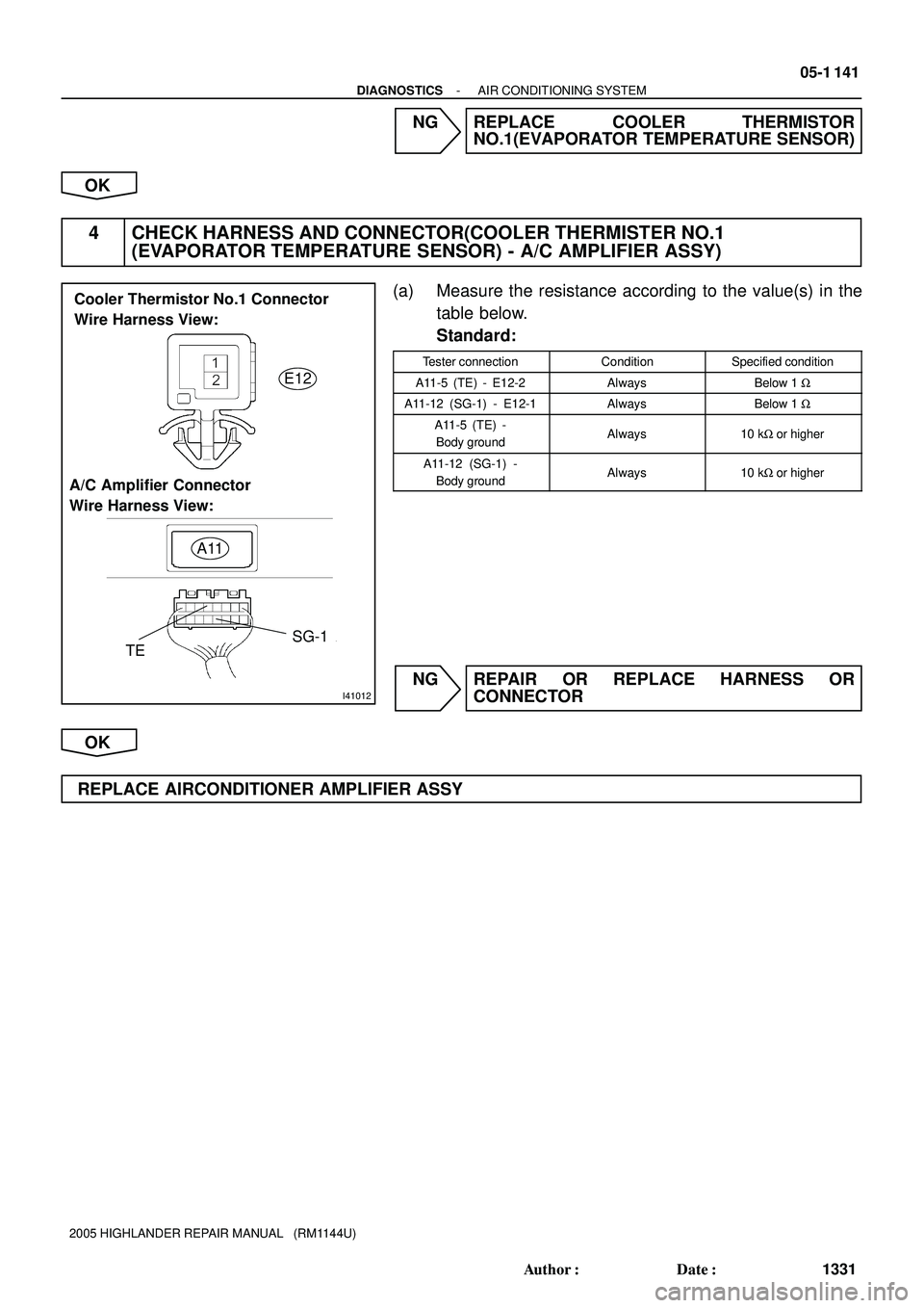
I41012
E12
A11
SG-1
TE A/C Amplifier Connector
Wire Harness View:
Cooler Thermistor No.1 Connector
Wire Harness View:
- DIAGNOSTICSAIR CONDITIONING SYSTEM
05-1 141
1331 Author�: Date�:
2005 HIGHLANDER REPAIR MANUAL (RM1144U)
NG REPLACE COOLER THERMISTOR
NO.1(EVAPORATOR TEMPERATURE SENSOR)
OK
4 CHECK HARNESS AND CONNECTOR(COOLER THERMISTER NO.1
(EVAPORATOR TEMPERATURE SENSOR) - A/C AMPLIFIER ASSY)
(a) Measure the resistance according to the value(s) in the
table below.
Standard:
Tester connectionConditionSpecified condition
A11-5 (TE) - E12-2AlwaysBelow 1 W
A11-12 (SG-1) - E12-1AlwaysBelow 1 W
A11-5 (TE) -
Body groundAlways10 kW or higher
A11-12 (SG-1) -
Body groundAlways10 kW or higher
NG REPAIR OR REPLACE HARNESS OR
CONNECTOR
OK
REPLACE AIRCONDITIONER AMPLIFIER ASSY
Page 1274 of 2572
Resistance of photodiode
Strength of solar radiationWeak Strong
High
Low
I30340
A/C Amplifier Assy
A12
Cooler (Solar sensor)
Thermistor
A11
S5-3 15 12L
A11 TS16
W 05-1 142
- DIAGNOSTICSAIR CONDITIONING SYSTEM
1332 Author�: Date�:
2005 HIGHLANDER REPAIR MANUAL (RM1144U)
DTC B1421/21 SOLAR SENSOR CIRCUIT (PASSENGER
SIDE)
CIRCUIT DESCRIPTION
A photo diode in the solar sensor detects solar radiation and
sends signals to the A/C amplifier assy.
DTC No.Detection ItemTrouble Area
Open or short in solar sensor circuit�Cooler (solar sensor) thermistor
B1421/21
Open or short in solar sensor circuit.
(Please note that display of DTC B1421/21 is not abnormal()
�Harness or connector between Cooler (solar sensor) Therm-
istor and A/C amplifier assy(Please note that dis lay of DTC B1421/21 is not abnormal
when the sensor is not receiving solar radiation.)istor and A/C amplifier assy
�A/C amplifier assy
WIRING DIAGRAM
05ITV-01
Page 1275 of 2572

S5-3 (-)
A/C Amplifier Connector
Wire Harness View:
A11
- DIAGNOSTICSAIR CONDITIONING SYSTEM
05-1 143
1333 Author�: Date�:
2005 HIGHLANDER REPAIR MANUAL (RM1144U)
INSPECTION PROCEDURE")
I30331
TS (+)
S5-3 (-)
A/C Amplifier Connector
Wire Harness View:
A11
- DIAGNOSTICSAIR CONDITIONING SYSTEM
05-1 143
1333 Author�: Date�:
2005 HIGHLANDER REPAIR MANUAL (RM1144U)
INSPECTION PROCEDURE
HINT:
In case of using the hand-held tester, start the inspection step 1 and in case of not using the hand-held
tester, start from step 2.
1 READ VALUE OF HAND-HELD TESTER
(a) Connect the hand-held tester to DLC3.
(b) Turn the ignition switch ON and push the hand-held tester main switch ON.
(c) Select the items below in the DATA LIST, and read the displays on the hand-held tester.
A C:
ItemMeasurement Item/Display
(Range)Normal ConditionDiagnostic Note
SOLAR SENS-PSolar sensor (Passenger side)
/min.: 0 max.: 255Changes depending on brightness
(Passenger side)-
Result:
NGA
OK (Checking from the DTC)B
OK (Checking from the PROBLEM SYMPTOM TABLE)C
B REPLACE AIRCONDITIONER AMPLIFIER ASSY
C PROCEED TO NEXT CIRCUIT INSPECTION
SHOWN IN PROBLEM SYMPTOMS TABLE(SEE
PAGE 05-1 129)
A
2 INSPECT AIRCONDITIONER AMPLIFIER ASSY(TS, S5-3)
(a) Remove A/C amplifier assy with connectors still con-
nected.
(b) Turn the ignition switch to the ON position.
(c) Measure the voltage according to the value(s) in the table
below.
Standard:
Tester connectionConditionSpecified condition
A11-16 (TS) -
A11-15 (S5-3)Sensor subject to electric
lightBelow 4.0 V
A11-16 (TS) -
A11-15 (S5-3)Sensor is covered by a
cloth4.0 to 4.5 V
HINT:
As the inspection light is moved away from the sensor, the volt-
age increases.
Use an incandescent lamp for inspection. Bring it within 30 cm
(11.8 in.) of the solar sensor.
OK PROCEED TO NEXT CIRCUIT INSPECTION
SHOWN IN PROBLEM SYMPTOMS TABLE(SEE
PAGE 05-1 129)
NG
Page 1276 of 2572

3 INSPECT COOLER (SOLAR SENSOR) THERMISTO")
I30886
Solar Sensor Connector
Front View:
A12
21
05-1 144
- DIAGNOSTICSAIR CONDITIONING SYSTEM
1334 Author�: Date�:
2005 HIGHLANDER REPAIR MANUAL (RM1144U)
3 INSPECT COOLER (SOLAR SENSOR) THERMISTOR
(a) Remove the cooler (solar sensor) thermistor.
(b) Measure the resistance according to the value(s) in the
table below.
(c) Connect the negative (-) lead from the ohmmeter to ter-
minal 1 and positive (+) lead to terminal 2 of the A/C solar
sensor.
Standard:
Tester connectionConditionSpecified condition
A12-1 - A12-2Sensor is subject to elec-
tric lightExcept 8 W
A12-1 - A12-2Sensor is covered with a
cloth8 W (No continuity)
NOTICE:
The connection procedure for using a digital tester such as
an electrical tester is shown above. When using an analog
tester, connect the negative (-) lead to terminal 2 and posi-
tive (+) lead to terminal 1 of the A/C solar sensor.
HINT:
�As the inspection light is moved away from the sensor, the
resistance increases.
�Use an incandescent lamp for inspection. Bring it within
30 cm (11.8 in.) of the cooler (solar sensor) thermistor.
NG REPLACE COOLER (SOLAR SENSOR)
THERMISTOR
OK


Thermistor
A11
S5-3 15 12L
A11 TS16
W 05-1 142
- DIAGNOSTICSAIR CONDITIONIN")