Page 1307 of 2572
G24991G26210
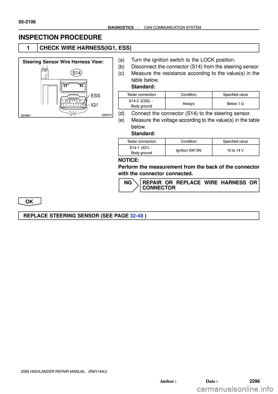
Steering Sensor Wire Harness View:
ESS
IG1 S14
05-2106
- DIAGNOSTICSCAN COMMUNICATION SYSTEM
2296 Author�: Date�:
2005 HIGHLANDER REPAIR MANUAL (RM1144U)
INSPECTION PROCEDURE
1 CHECK WIRE HARNESS(IG1, ESS)
(a) Turn the ignition switch to the LOCK position.
(b) Disconnect the connector (S14) from the steering sensor.
(c) Measure the resistance according to the value(s) in the
table below.
Standard:
Tester connectionConditionSpecified value
S14-2 (ESS) -
Body groundAlwaysBelow 1 W
(d) Connect the connector (S14) to the steering sensor.
(e) Measure the voltage according to the value(s) in the table
below.
Standard:
Tester connectionConditionSpecified value
S14-1 (IG1) -
Body groundIgnition SW ON10 to 14 V
NOTICE:
Perform the measurement from the back of the connector
with the connector connected.
NG REPAIR OR REPLACE WIRE HARNESS OR
CONNECTOR
OK
REPLACE STEERING SENSOR (SEE PAGE 32-48)
Page 1308 of 2572

G30959
4J4C
Battery FL MAINPassenger Side J/BY1
Yaw Rate Sensor
IG
GND 42
5CANH
CANL
2 3 YAW
YAW J16
J/C
9
20
Y
F7 FL Block
ALTInstrument Panel J/B
1A 1D
1C 1C 10
17
6 ECU-IG
AM1
12G
W4
BF WG
12 WB2 I15
Ignition SW
IG1 AM1WB
IO2
IO212
13
O
AA W-B W-BJ19
J/C
1 3
IO2 V
- DIAGNOSTICSCAN COMMUNICATION SYSTEM
05-2107
2297 Author�: Date�:
2005 HIGHLANDER REPAIR MANUAL (RM1144U)
YAW RATE SENSOR COMMUNICATION STOP MODE
CIRCUIT DESCRIPTION
DTC No.DTC Detecting ConditionTrouble Area
U0123/62
�When ECU terminal IG1 voltage is 9.5 V or more, data is
not received from the yaw rate sensor for more than 1
sec.
�When ECU terminal IG1 voltage is 9.5 V or more, data
can not be received from the yaw rate sensor more than
once within 5 sec .This situation repeatedly occurs more
than 10 times.
�Yaw rate sensor
�Yaw rate sensor sub bus line
�Power source of yaw rate sensor
U0124/95
�When ECU terminal IG1 voltage is 9.5 V or more, data is
not received from the deceleration the sensor for more
than 1 sec.
�When ECU terminal IG1 voltage is 9.5 V or more, data
can not be received from the deceleration sensor more
than once within 5 sec. This situation repeatedly occurs
more than 10 times.
�Yaw rate sensor
�Yaw rate sensor sub bus line
�Power source of yaw rate sensor
WIRING DIAGRAM
05DY8-04
Page 1309 of 2572

G26359
Yaw Rate Sensor Connector
Front View:
CANLCANH
Y1
G26359
Yaw Rate Sensor Connector
Front View:
IG
GND
Y1
05-2108
- DIAGNOSTICSCAN COMMUNICATION SYSTEM
2298 Author�: Date�:
2005 HIGHLANDER REPAIR MANUAL (RM1144U)
INSPECTION PROCEDURE
1 CHECK CAN BUS LINE FOR DISCONNECTION(YAW RATE SENSOR SUB BUS
LINE)
(a) Turn the ignition switch to the LOCK position.
(b) Disconnect the connector (Y1) from the yaw rate sensor.
(c) Measure the resistance according to the value(s) in the
table below.
Standard:
Tester connectionConditionSpecified value
Y1-2 (CANL) -
Y1-3 (CANH)Ignition SW OFF54 to 69 W
NG REPAIR OR REPLACE YAW RATE SENSOR SUB
BUS LINE OR CONNECTOR (CAN-H, CAN-L)
OK
2 CHECK WIRE HARNESS(IG,GND)
(a) Measure the resistance according to the value(s) in the
table below.
Standard:
Tester connectionConditionSpecified value
Y1-1 (GND) -
Body groundAlwaysBelow 1 W
(b) Measure the voltage according to the value(s) in the table
below.
Standard:
Tester connectionConditionSpecified value
Y1-5 (IG) - Body groundIgnition SW ON10 to 14 V
NG REPAIR OR REPLACE HARNESS OR
CONNECTOR
OK
REPLACE YAW RATE SENSOR (SEE PAGE 32-46)
Page 1310 of 2572
G30960
S14
Steering Sensor
CANL CANH
10
9CANL CANH J16
J/CSkid Control ECU
with Actuator
Y
W10
21STRGVSC
VSC
STRG8
19L
W12
IC4
IC413B
W11
S27
S2725
- DIAGNOSTICSCAN COMMUNICATION SYSTEM
05-2109
2299 Author�: Date�:
2005 HIGHLANDER REPAIR MANUAL (RM1144U)
CHECK CAN MAIN BUS LINE FOR DISCONNECTION
CIRCUIT DESCRIPTION
The CAN main bus line and DLC3 sub bus line may have a disconnection when the resistance between ter-
minals 6 (CANH) and 14 (CANL) of the DLC3 is more than 69 W.
SymptomTrouble Area
Resistance between terminals 6 (CANH) and 14 (CANL) of
DLC3 is more than 69 W .�CAN main bus line
�Skid control ECU
�Steering sensor
WIRING DIAGRAM
05DY7-1 1
Page 1312 of 2572

E69126
Skid Control ECU Connector
Front View:
CANH
CANL
S27
G24991G26210
Steering Sensor Wire Harness View:
S14
CANH
CANL
- DIAGNOSTICSCAN COMMUNICATION SYSTEM
05-21 11
2301 Author�: Date�:
2005 HIGHLANDER REPAIR MANUAL (RM1144U)
3 CHECK CAN MAIN BUS LINE FOR DISCONNECTION(SKID CONTROL ECU -
JUNCTION CONNECTOR)
(a) Disconnect the connector (S27) from the skid control
ECU.
(b) Measure the resistance according to the value(s) in the
table below.
Standard:
Tester connectionConditionSpecified value
S27-1 1 (CANH) -
S27-25 (CANL)Ignition SW OFF108 to 132 W
NG REPAIR OR REPLACE CAN MAIN BUS LINE OR
CONNECTOR (SKID CONTROL ECU - JUNC-
TION CONNECTOR)
OK
REPLACE SKID CONTROL ECU WITH ACTUATOR (SEE PAGE 32-37)
4 CHECK CAN MAIN BUS LINE FOR DISCONNECTION(STEERING SENSOR -
JUNCTION CONNECTOR)
(a) Turn the ignition switch to the LOCK position.
(b) Disconnect the connector (S14) from the steering sensor.
(c) Measure the resistance according to the value(s) in the
table below.
Standard:
Tester connectionConditionSpecified value
S14-10 (CANH) -
S14-9 (CANL)Ignition SW OFF108 to 132 W
NG REPAIR OR REPLACE CAN MAIN BUS LINE OR
CONNECTOR (STEERING SENSOR - JUNC-
TION CONNECTOR)
OK
REPLACE STEERING SENSOR (SEE PAGE 32-48)
Page 1313 of 2572
G30961
S14
Steering Sensor
CANL CANH
9CANL CANH J16
J/CSkid Control ECU
with Actuator
Y1
Yaw Rate Sensor
CANL CANH
3
2Y
W10
21
B
WG
W 12
IO2
IO29
20STRGVSC
VSC
STRG
YAW8
19L
W12
IC4
IC413B
W11
S27
S2725
13YAW 10 05-21 12
- DIAGNOSTICSCAN COMMUNICATION SYSTEM
2302 Author�: Date�:
2005 HIGHLANDER REPAIR MANUAL (RM1144U)
CHECK CAN BUS LINES FOR SHORT CIRCUIT
CIRCUIT DESCRIPTION
The CAN bus lines are considered to be shorted when the resistance between terminals 6 (CANH) and 14
(CANL) of the DLC3 is below 54 W.
SymptomTrouble Area
Resistance between terminals 6 (CANH) and 14 (CANL) of
DLC3 is below 54 W.
�Short in CAN bus lines
�Skid control ECU
�Steering sensor
�Yaw rate sensor
WIRING DIAGRAM
05IR3-02
Page 1315 of 2572

G26199G28087
Skid Control ECU:
CANH
CANL
G24991G26210
Steering Sensor Wire Harness View:
S14
CANH
CANL
G24692 G25475G26209
Steering Sensor:
CANH CANL
05-21 14
- DIAGNOSTICSCAN COMMUNICATION SYSTEM
2304 Author�: Date�:
2005 HIGHLANDER REPAIR MANUAL (RM1144U)
3 INSPECT SKID CONTROL ECU WITH ACTUATOR(CANH - CANL)
(a) Measure the resistance according to the value(s) in the
table below.
Standard:
Tester connectionConditionSpecified value
11 (CANH) - 25 (CANL)Ignition SW OFF108 to 132 W
NG REPLACE SKID CONTROL ECU WITH
ACTUATOR (SEE PAGE 32-37)
OK
4 CHECK CAN BUS LINES FOR SHORT(STEERING SENSOR - JUNCTION
CONNECTOR)
(a) Disconnect the connector (S14) from the steering sensor.
(b) Measure the resistance according to the value(s) in the
table below.
Standard:
Tester connectionConditionSpecified value
S14-10 (CANH) -
S14-9 (CANL)Ignition SW OFF1 MW or more
HINT:
Check the wire harness connector connected to the junction
connector while disconnecting it.
NG REPAIR OR REPLACE STEERING SENSOR
SUB BUS LINE OR CONNECTOR (CAN-H,
CAN-L)
OK
5 INSPECT STEERING SENSOR(CANH - CANL)
(a) Measure the resistance according to the value(s) in the
table below.
Standard:
Tester connectionConditionSpecified value
10 (CANH) - 9 (CANL)Ignition SW OFF108 to 132 W
NG REPLACE STEERING SENSOR
(SEE PAGE 32-48)
OK
Page 1316 of 2572
G26359
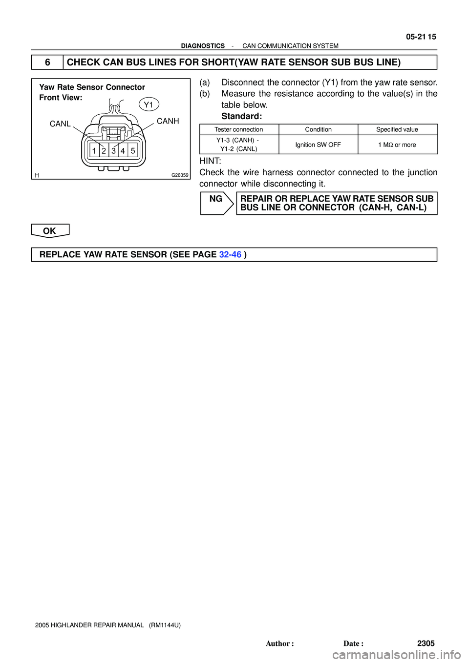
Yaw Rate Sensor Connector
Front View:
CANLCANH
Y1
- DIAGNOSTICSCAN COMMUNICATION SYSTEM
05-21 15
2305 Author�: Date�:
2005 HIGHLANDER REPAIR MANUAL (RM1144U)
6 CHECK CAN BUS LINES FOR SHORT(YAW RATE SENSOR SUB BUS LINE)
(a) Disconnect the connector (Y1) from the yaw rate sensor.
(b) Measure the resistance according to the value(s) in the
table below.
Standard:
Tester connectionConditionSpecified value
Y1-3 (CANH) -
Y1-2 (CANL)Ignition SW OFF1 MW or more
HINT:
Check the wire harness connector connected to the junction
connector while disconnecting it.
NG REPAIR OR REPLACE YAW RATE SENSOR SUB
BUS LINE OR CONNECTOR (CAN-H, CAN-L)
OK
REPLACE YAW RATE SENSOR (SEE PAGE 32-46)