Page 1246 of 2572
B51843
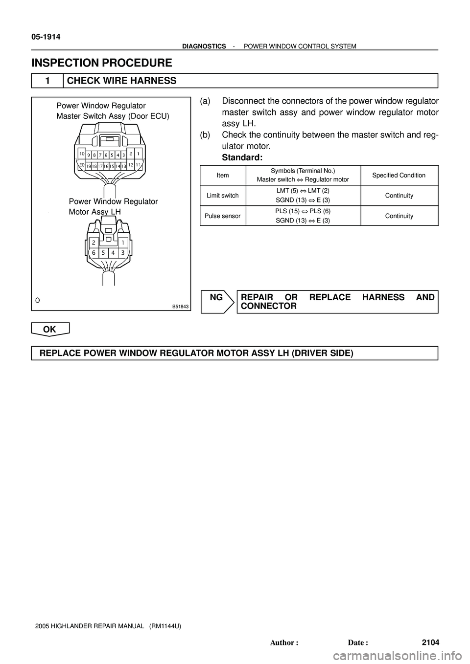
Power Window Regulator
Master Switch Assy (Door ECU)
Power Window Regulator
Motor Assy LH
05-1914
- DIAGNOSTICSPOWER WINDOW CONTROL SYSTEM
2104 Author�: Date�:
2005 HIGHLANDER REPAIR MANUAL (RM1144U)
INSPECTION PROCEDURE
1 CHECK WIRE HARNESS
(a) Disconnect the connectors of the power window regulator
master switch assy and power window regulator motor
assy LH.
(b) Check the continuity between the master switch and reg-
ulator motor.
Standard:
ItemSymbols (Terminal No.)
Master switch @ Regulator motorSpecified Condition
Limit switchLMT (5) @LMT (2)
SGND (13) @ E (3)Continuity
Pulse sensorPLS (15) @ PLS (6)
SGND (13) @ E (3)Continuity
NG REPAIR OR REPLACE HARNESS AND
CONNECTOR
OK
REPLACE POWER WINDOW REGULATOR MOTOR ASSY LH
(DRIVER SIDE)
Page 1262 of 2572
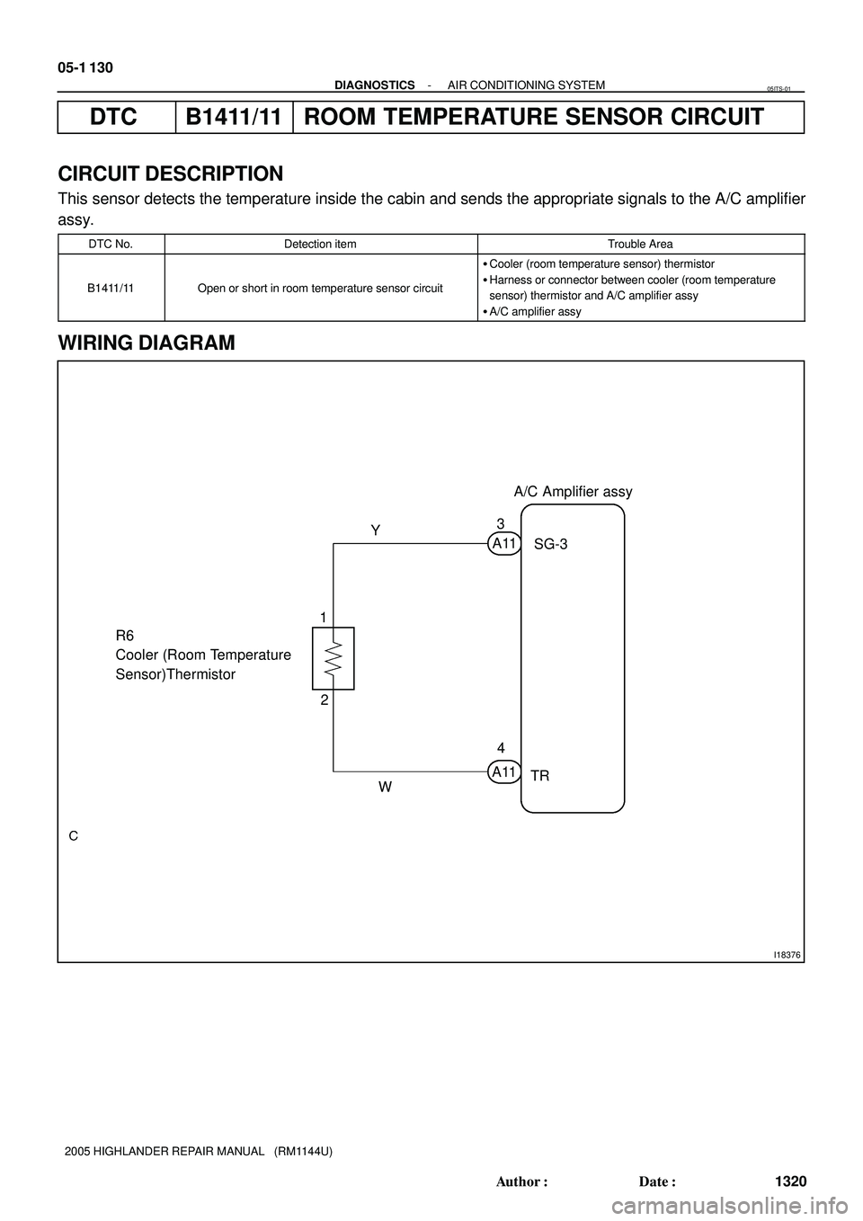
I18376
A/C Amplifier assy
SG-3
TR A11A113
4 Y
W R6
Cooler (Room Temperature
Sensor)Thermistor1
2 05-1 130
- DIAGNOSTICSAIR CONDITIONING SYSTEM
1320 Author�: Date�:
2005 HIGHLANDER REPAIR MANUAL (RM1144U)
DTC B1411/11 ROOM TEMPERATURE SENSOR CIRCUIT
CIRCUIT DESCRIPTION
This sensor detects the temperature inside the cabin and sends the appropriate signals to the A/C amplifier
assy.
DTC No.Detection itemTrouble Area
B1411/11Open or short in room temperature sensor circuit
�Cooler (room temperature sensor) thermistor
�Harness or connector between cooler (room temperature
sensor) thermistor and A/C amplifier assy
�A/C amplifier assy
WIRING DIAGRAM
05ITS-01
Page 1263 of 2572
 TR (+)
A/C Amplifier Connector
Wire Harness View:
A11
- DIAGNOSTICSAIR CONDITIONING SYSTEM
05-1 131
1321 Author�: Date�:
2005 HIGHLANDER REPAIR MANUAL (RM1144U)
INSPECTION PROCEDURE")
I30331SG-3 (-) TR (+)
A/C Amplifier Connector
Wire Harness View:
A11
- DIAGNOSTICSAIR CONDITIONING SYSTEM
05-1 131
1321 Author�: Date�:
2005 HIGHLANDER REPAIR MANUAL (RM1144U)
INSPECTION PROCEDURE
HINT:
In case of using the hand-held tester, start the inspection step 1 and in case of not using the hand-held
tester, start from step 2.
1 READ VALUE OF HAND-HELD TESTER
(a) Connect the hand-held tester to the DLC3.
(b) Turn the ignition switch ON and push the hand-held tester main switch ON.
(c) Select the items below in the DATA LIST,and read the displays on the hand-held tester.
A C:
ItemMeasurement Item/Display
(Range)Normal ConditionDiagnostic Note
ROOM TEMP
Room temperature sensor
/min.: -6.5�C (20.3�F)
max.: 57.25�C (135.05�F)
Actual room temperature-
Result:
NGA
OK (Checking from the DTC)B
OK (Checking from the PROBLEM SYMPTOM TABLE)C
B REPLACE AIRCONDITIONER AMPLIFIER ASSY
C PROCEED TO NEXT CIRCUIT INSPECTION
SHOWN IN PROBLEM SYMPTOMS TABLE (SEE
PAGE 05-1 129)
A
2 INSPECT AIRCONDITIONER AMPLIFIER ASSY(TR, SG-3)
(a) Remove A/C amplifier assy with connectors still con-
nected.
(b) Turn the ignition switch to the ON position.
(c) Measure the voltage according to the value(s) in the table
below.
Standard:
Tester connectionConditionSpecified condition
A11-3 (SG-3) -
A11-4 (TR)at 25�C (77�F)1.8 to 2.2 V
A11-3 (SG-3) -
A11-4 (TR)at 40�C (104�F)1.2 to 1.6 V
HINT:
As the temperature increases, the voltage decreases.
OK REPLACE AIRCONDITIONER AMPLIFIER ASSY
NG
Page 1264 of 2572

Temperature 6810460 (
5C)
140 (
5F)
32Maximum permissible value line
Minimum")
I30111
Cooler Thermistor Connector
Front View:
R6
I38777I40673
4.0
3.5
3.0
2.5
2.0
1.5
1.0
0.0 0.5
020 40 Resistance
(kW)
Temperature 6810460 (
5C)
140 (
5F)
32Maximum permissible value line
Minimum permissible value line
05-1 132
- DIAGNOSTICSAIR CONDITIONING SYSTEM
1322 Author�: Date�:
2005 HIGHLANDER REPAIR MANUAL (RM1144U)
3 INSPECT COOLER (ROOM TEMP. SENSOR) THERMISTOR
(a) Remove cooler (room temperature sensor) thermistor.
(b) Measure the resistance according to the value(s) in the
table below.
Standard:
Tester connectionConditionSpecified condition
R6-1 - R6-2105C (505F)3.00 to 3.73 kW
R6-1 - R6-2155C (595F)2.45 to 2.88 kW
R6-1 - R6-2205F (685F)1.95 to 2.30 kW
R6-1 - R6-2255C (775F)1.60 to 1.80 kW
R6-1 - R6-2305C (865F)1.28 to 1.47 kW
R6-1 - R6-2355C (955F)1.00 to 1.22 kW
R6-1 - R6-2405C (1045F)0.80 to 1.00 kW
R6-1 - R6-2455C (1135F)0.65 to 0.85 kW
R6-1 - R6-2505C (1225F)0.50 to 0.70 kW
R6-1 - R6-2555C (1315F)0.44 to 0.60 kW
R6-1 - R6-2605C (1405F)0.36 to 0.50 kW
NOTICE:
�Even slightly touching the sensor may change the re-
sistance value. Be sure to hold the connector of the
sensor.
�When measuring the sensor temperature must be the
same as the ambient temperature.
HINT:
As the temperature increases, the resistance decreases (see
the chart below).
Page 1265 of 2572
I41011
R6
A11
Cooler (Room Temperature Sensor)
Thermistor Connector Front View:
A/C Amplifier Connector
Wire Harness View:
TRSG-3
- DIAGNOSTICSAIR CONDITIONING SYSTEM
05-1 133
1323 Author�: Date�:
2005 HIGHLANDER REPAIR MANUAL (RM1144U)
NG REPLACE COOLER (ROOM TEMP. SENSOR)
THERMISTOR
OK
4 CHECK HARNESS AND CONNECTOR(COOLER (ROOM TEMPERATURE SENSOR)
THERMISTOR - A/C AMPLIFIER ASSY)
(a) Measure the resistance according to the value(s) in the
table below.
Standard:
Tester connectionConditionSpecified condition
A11-4 (TR) - R6-2AlwaysBelow 1 W
A11-3 (SG-3) - R6-1AlwaysBelow 1 W
A11-4 (TR) -
Body groundAlways10 kW or higher
A11-3 (SG-3) -
Body groundAlways10 kW or higher
NG REPAIR OR REPLACE HARNESS OR
CONNECTOR
OK
REPLACE AIRCONDITIONER AMPLIFIER ASSY
Page 1266 of 2572
I38775
A/C Amplifier assy
TA M A1
Cooler (Ambient Temperature
Sensor) Thermistor
2 1
B-R BR
E2
E6E7 S29 S28
B 5
IK3 EB26Short Connector
BR A11
A109 2
MPX+
MPX-E6
E629 18
MPX1
MPX2
3228 5 5ECM
BR BEAN signal 05-1 134
- DIAGNOSTICSAIR CONDITIONING SYSTEM
1324 Author�: Date�:
2005 HIGHLANDER REPAIR MANUAL (RM1144U)
DTC B1412/12 AMBIENT TEMPERATURE SENSOR CIRCUIT
CIRCUIT DESCRIPTION
The ECM and A/C amplifier communicate via BEAN.
This sensor detects the temperature outside the cabin and sends the appropriate signals to the A/C amplifier
assy.
DTC No.Detection itemTrouble Area
B1412/12Open or short in ambient temperature sensor circuit
�Cooler (ambient temperature sensor) thermistor
�Harness or connector between cooler (ambient temperature
sensor) thermistor and ECM
�ECM
�A/C amplifier assy
WIRING DIAGRAM
05ITT-01
Page 1267 of 2572
 E2 (-)
ECM Connector Wire Harness View:
E6E7
- DIAGNOSTICSAIR CONDITIONING SYSTEM
05-1 135
1325 Author�: Date�:
2005 HIGHLANDER REPAIR MANUAL (RM1144U)
INSPECTION PROCEDURE
HINT:
In c")
I38774
TAM (+) E2 (-)
ECM Connector Wire Harness View:
E6E7
- DIAGNOSTICSAIR CONDITIONING SYSTEM
05-1 135
1325 Author�: Date�:
2005 HIGHLANDER REPAIR MANUAL (RM1144U)
INSPECTION PROCEDURE
HINT:
In case of using the hand-held tester, start the inspection step 1 and in case of not using the hand-held
tester, start from step 2.
1 READ VALUE OF HAND-HELD TESTER
(a) Connect the hand-held tester to the DLC3.
(b) Turn the ignition switch ON and push the hand-held tester main switch ON.
(c) Select the items below in the DATA LIST, and read the displays on the hand-held tester.
A C:
ItemMeasurement Item/Display
(Range)Normal ConditionDiagnostic Note
AMBI TEMP SENS
Ambient temperature sensor
/min.: -23.3�C (-9.94�F)
max.: 65.95�C (150.71�F)
Actual ambient temperature-
AMBI TEMP
adjusted ambient temperature
/min.: -30.8�C (-23.44�F)
max.: 50.8�C (123.44�F)
Actual ambient temperature-
Result:
NGA
OK (Checking from the DTC)B
OK (Checking from the PROBLEM SYMPTOM TABLE)C
B REPLACE ECM
C PROCEED TO NEXT CIRCUIT INSPECTION
SHOWN IN PROBLEM SYMPTOMS TABLE(SEE
PAGE 05-1 129)
A
2 INSPECT ECM(TAM, E2)
(a) Remove ECM with connectors still connected.
(b) Turn ignition switch ON.
(c) Measure the voltage according to the value(s) in the table
below.
Standard:
Tester connectionConditionSpecified condition
E6-32 (TAM) -
E7-28 (E2)at 25�C (77�F)1.4 to 1.8 V
E6-32 (TAM) -
E7-28 (E2)at 40�C (104�F)0.8 to 1.2 V
HINT:
As the temperature increases, the voltage decreases.
OK REPLACE ECM
NG
Page 1268 of 2572

Temperature 6810460 (
5C)
140 (
5F)
32Maximum permissible value li")
I30487
12A1 Ambient Temperature Sensor
Connector Front View:
I38777I40673
4.0
3.5
3.0
2.5
2.0
1.5
1.0
0.0 0.5
020 40 Resistance
(kW)
Temperature 6810460 (
5C)
140 (
5F)
32Maximum permissible value line
Minimum permissible value line
05-1 136
- DIAGNOSTICSAIR CONDITIONING SYSTEM
1326 Author�: Date�:
2005 HIGHLANDER REPAIR MANUAL (RM1144U)
3 INSPECT COOLER (AMBIENT TEMP. SENSOR) THERMISTOR
(a) Remove cooler (ambient temperature sensor) thermistor.
(b) Measure the resistance according to the value(s) in the
table below.
Standard:
Tester connectionConditionSpecified condition
A1-1 - A1-2105C (505F)3.00 to 3.73 kW
A1-1 - A1-2155C (595F)2.45 to 2.88 kW
A1-1 - A1-2205F (685F)1.95 to 2.30 kW
A1-1 - A1-2255C (775F)1.60 to 1.80 kW
A1-1 - A1-2305C (865F)1.28 to 1.47 kW
A1-1 - A1-2355C (955F)1.00 to 1.22 kW
A1-1 - A1-2405C (1045F)0.80 to 1.00 kW
A1-1 - A1-2455C (1135F)0.65 to 0.85 kW
A1-1 - A1-2505C (1225F)0.50 to 0.70 kW
A1-1 - A1-2555C (1315F)0.44 to 0.60 kW
A1-1 - A1-2605C (1405F)0.36 to 0.50 kW
NOTICE:
�Even slightly touching the sensor may change the re-
sistance value. Be sure to hold the connector of the
sensor.
�When measuring the sensor temperature must be the
same as the ambient temperature.
HINT:
As the temperature increases, the resistance decreases (see
the chart below).
 Thermistor
2 1
B-R BR
E2
E6E7 S29 S28
B 5
IK3 EB26Short Connector
BR A11
A109 2
MPX+
MPX-E6
E629 18
MPX1
MPX2
3228 5 5ECM
BR BEAN")