Page 1277 of 2572
I41013
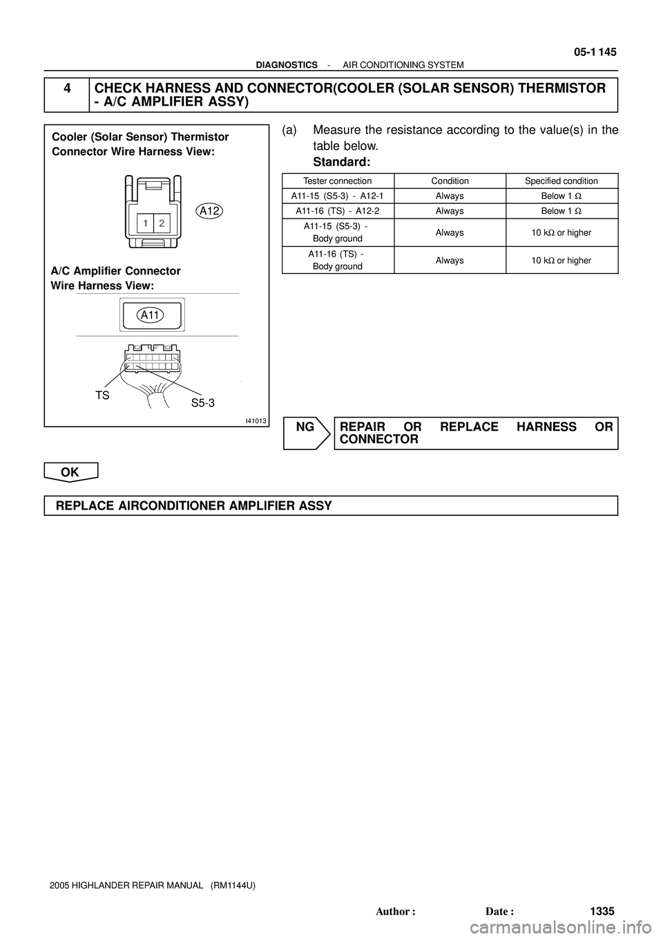
A12
A11
Cooler (Solar Sensor) Thermistor
Connector Wire Harness View:
A/C Amplifier Connector
Wire Harness View:
TS
S5-3
- DIAGNOSTICSAIR CONDITIONING SYSTEM
05-1 145
1335 Author�: Date�:
2005 HIGHLANDER REPAIR MANUAL (RM1144U)
4 CHECK HARNESS AND CONNECTOR(COOLER (SOLAR SENSOR) THERMISTOR
- A/C AMPLIFIER ASSY)
(a) Measure the resistance according to the value(s) in the
table below.
Standard:
Tester connectionConditionSpecified condition
A11-15 (S5-3) - A12-1AlwaysBelow 1 W
A11-16 (TS) - A12-2AlwaysBelow 1 W
A11-15 (S5-3) -
Body groundAlways10 kW or higher
A11-16 (TS) -
Body groundAlways10 kW or higher
NG REPAIR OR REPLACE HARNESS OR
CONNECTOR
OK
REPLACE AIRCONDITIONER AMPLIFIER ASSY
Page 1278 of 2572

ED
EEBR (*1)
*1: 3MZ-FE
*2: 2AZ-FE 05-1 146
- DIAGNOSTICSAIR CONDITIONING SYSTEM
1336 Author�: Date�:
2005 HIGHLANDER REPAI")
I38769
ECM
LCK1 23
E9 W-L
A2
Cooler
Compressor
Assy
J7
J/C 1
2
A
ABR
BR (*2)
ED
EEBR (*1)
*1: 3MZ-FE
*2: 2AZ-FE 05-1 146
- DIAGNOSTICSAIR CONDITIONING SYSTEM
1336 Author�: Date�:
2005 HIGHLANDER REPAIR MANUAL (RM1144U)
DTC B1422/22 COMPRESSOR LOCK SENSOR CIRCUIT
CIRCUIT DESCRIPTION
The ECM and A/C amplifier communicate via BEAN.
This sensor sends 4 pulses per engine revolution to the ECM.
If the number ratio of the compressor speed divided by the engine speed is smaller than a predetermined
value, the ECM turns the compressor OFF. And the indicator flashes at about 1 second intervals.
DTC No.Detection ItemTrouble Area
All conditions below are detected for 3 secs or more
�Cooler compressor assy (A/C magnetic clutch and lock sen-
sor)
�
Cooler compressor assy drive belt
B1422/22
All conditions below are detected for 3 secs. or more
(c) Engine speed: 450 rpm or more
(d) Ratio between engine and compressor speed deviates
20 % or more in comparison to normal operation
�Cooler com ressor assy drive belt
�Cooler compressor assy lock sensor
�Harness and connector between cooler compressor assy and
ECM
20 % or more in comparison to normal operation.ECM
�Multiplex communication circuit
�ECM
�A/C amplifier assy
WIRING DIAGRAM
05ITW-01
Page 1281 of 2572
 Low pressure side High pressure side
OFF
(10 kW or higher)OFF
(10 kW or higher) (2.0 kgfVcm
2, 28 psi) (32.0 kgfVcm2, 455 psi) 196 KPa 3,140 KPa
I41168
HP E61ECM
IK32
L G
1 A")
I40666
ON (Below 1.0 W) Low pressure side High pressure side
OFF
(10 kW or higher)OFF
(10 kW or higher) (2.0 kgfVcm
2, 28 psi) (32.0 kgfVcm2, 455 psi) 196 KPa 3,140 KPa
I41168
HP E61ECM
IK32
L G
1 A3
Pressure Switch
4
A
EH J2
J/CW-B
Dual
- DIAGNOSTICSAIR CONDITIONING SYSTEM
05-1 149
1339 Author�: Date�:
2005 HIGHLANDER REPAIR MANUAL (RM1144U)
DTC B1423/23 PRESSURE SWITCH CIRCUIT
CIRCUIT DESCRIPTION
The ECM and A/C amplifier communicate via BEAN.
The pressure switch sends the appropriate signals to the A/C
amplifier when the A/C refrigerant pressure drops too low or
rises too high. When the A/C amplifier receives these signals,
it outputs signals through the A/C amplifier to turn the magnet
clutch relay off and turns the magnetic clutch off.
DTC No.Detection ItemTrouble Area
B1423/23
�Open in pressure sensor circuit.
�Abnormal refrigerant pressure.
below 196 kPa (2.0 kg/cm
2, 28 psi)
over 3,140 kPa (32.0 kgf/cm2, 455 psi)
�Pressure switch
�Harness or connector between cooler refrigerant liquid pipe A
(pressure switch) and ECM
�Multiplex communication circuit
�Refrigerant pipe line
�ECM
�A/C amplifier assy
WIRING DIAGRAM
05ITX-02
Page 1284 of 2572
4
1
0
100%
TP terminal voltage (V)
Damper opening angle
I30342
A14
A/C Amplifier Assy
P
SB 1
S5-1SG-1
TP 1012
3 2
11
A11 A11
A11 O
AMH
13 14
A11A11
AMC B
GR 45
Y Y-GO P-L LG-R
IJ1
IJ1
IJ1
IJ1
IJ13
4
1
2 5 Air Mix Damper Servo Sub-assy 05-1 152
- DIAGNOSTICSAIR CONDITIONING SYSTEM
1342 Author�: Date�:
2005 HIGHLANDER REPAIR MANUAL (RM1144U)
DTC B1431/31 AIR MIX DAMPER POSITION SENSOR
CIRCUIT (PASSENGER SIDE)
CIRCUIT DESCRIPTION
This sensor detects the position of the air mix damper servo
sub-assy and sends the appropriate signals to the A/C amplifi-
er assy. The position sensor is built into the air mix servo sub-
assy.
DTC No.Detection ItemTrouble Area
B1431/31Short to ground or power source circuit in air mix damper posi-
tion sensor circuit.
�Air mix damper position sensor.
�Harness or connector between air mix damper servo sub-
assy and A/C amplifier assy.
�A/C amplifier assy
WIRING DIAGRAM
05ITY-01
Page 1288 of 2572
TPO terminal voltage
(V)
4
1
0 100%
Damper opening angle
I30342
Mode Damper Servo Sub-assy
(Air Outlet Damper Position Sensor)A/C Amplifier Assy
1
S5-4 SG-4
TPO 6
8 3
2
7 A11
AOF
AOD 49 1
A11
A11
A11
A11 B
BR
R
V
G IL2
IL2
IL2
IL2
IL2 13
14
15 3
5
4W
B
G
LG
L A15 05-1 156
- DIAGNOSTICSAIR CONDITIONING SYSTEM
1346 Author�: Date�:
2005 HIGHLANDER REPAIR MANUAL (RM1144U)
DTC B1433/33 AIR OUTLET DAMPER POSITION SENSOR
CIRCUIT
CIRCUIT DESCRIPTION
This sensor detects the position of the mode damper servo
sub-assy and sends the appropriate signals to the A/C amplifi-
er assy. The position sensor is built into the mode damper servo
sub-assy .
DTC No.Detection ItemTrouble Area
B1433/33Short to ground or power source circuit in air outlet damper
position sensor circuit.
�Mode damper position sensor (Air outlet damper position
sensor)
�Harness or connector between mode damper servo sub-
assy and A/C amplifier assy
�A/C amplifier assy
WIRING DIAGRAM
05ITZ-02
Page 1292 of 2572

I30342
1
S5-1 SG-1
TP 12
3 2
A11
AMH
AMC 4 5A/C Amplifier Assy
A11
A11
A11 A1111
10
14
13 P
O
SB
B 3
4
5
1
2
IJ1IJ1IJ1 IJ1
IJ1 LG-R
P-L
GR Y Y-GO A14 Air Mix Damper Servo Sub-assy 05-1 160
- DIAGNOSTICSAIR CONDITIONING SYSTEM
1350 Author�: Date�:
2005 HIGHLANDER REPAIR MANUAL (RM1144U)
DTC B1441/41 AIR MIX DAMPER CONTROL SERVOMOTOR
CIRCUIT (PASSENGER SIDE)
CIRCUIT DESCRIPTION
This air mix damper servo sub-assy is controlled by the A/C amplifier assy and moves the air mix damper
servo sub-assy to the desired position.
DTC No.Detection ItemTrouble Area
�Air mix damper servo sub-assy
B1441/41Air mix damper position sensor value does not change even if
�Air mix damper servo sub-assy
�Harness or connector between air mix damper servo sub-B1441/41Air mix dam er osition sensor value does not change even if
A/C amplifier assy operates air mix damper servo sub-assy.
�Harness or connector between air mix dam er servo sub-
assy and A/C amplifier assyA/C am lifier assy o erates air mix dam er servo sub assy.assy and A/C am lifier assy
�A/C amplifier assy
WIRING DIAGRAM
05IU0-01
Page 1296 of 2572

I30342
A15
Mode Damper Servo Sub-assy
A/C Amplifier Assy
IL2 1
S5-4 SG-4
TPO 6 1
3 29
BRA11 B
AOD 8 R
AOF
45A11
A11
A11
A117 V
G 13
3
14
15
4 IL2
IL2
IL2
IL2 W
B
G
LG
L 05-1 164
- DIAGNOSTICSAIR CONDITIONING SYSTEM
1354 Author�: Date�:
2005 HIGHLANDER REPAIR MANUAL (RM1144U)
DTC B1443/43 AIR OUTLET DAMPER CONTROL
SERVOMOTOR CIRCUIT
CIRCUIT DESCRIPTION
This circuit turns the servomotor and changes each mode damper position by the signals from the A/C ampli-
fier assy. When the AUTO switch is on, the A/C amplifier assy changes the mode automatically between
(FACE), (BI-LEVEL) and (FOOT) according to the temperature setting.
DTC No.Detection ItemTrouble Area
�Mode damper servo sub-assy.
B1443/43
Air outlet damper position sensor value does not change even
if A/C lifi t i d d b
�Mode damper servo sub-assy.
�Harness or connector between mode damper servo sub-
B1443/43if A/C amplifier assy operates air mode damper servo sub-
assy
�Harness or connector between mode dam er servo sub-
assy and A/C amplifier assy.assy.assy and A/C am lifier assy.
�A/C amplifier assy.
WIRING DIAGRAM
05IU1-01
Page 1306 of 2572
G30958
4L 4J
4C 4C
W-B
Battery FL MAINPassenger Side J/BS14
Steering Sensor
IG1
ESS 4
711
3
2 1CANH
CANL
9 10
W-BL STRG
STRG J16
J/C
10
21
Y
F7 FL Block
ALTInstrument Panel J/B
1A1D
1C1C 10
17
6 ECU-IG
AM1
12G
W4
IC WY
12 WB2 I15
Ignition SW
IG1 AM1
- DIAGNOSTICSCAN COMMUNICATION SYSTEM
05-2105
2295 Author�: Date�:
2005 HIGHLANDER REPAIR MANUAL (RM1144U)
STEERING SENSOR COMMUNICATION STOP MODE
CIRCUIT DESCRIPTION
DTC No.DTC Detecting ConditionTrouble Area
U0126/63
�When ECU terminal IG1 voltage is 9.5 V or more, data is
not received from the steering sensor for more than 1 sec.
�When ECU terminal IG1 voltage is 9.5 V or more, data
can not be received from the steering sensor more than
once within 5 sec. This situation repeatedly occurs more
than 10 times.
�Steering sensor
�Power source of steering sensor
WIRING DIAGRAM
05IR2-02

Damper opening angle
I30342
A14
A/C Amplifier Assy
P
SB 1
S5-1SG-1
TP 1012
3 2
11
A11 A11
A11 O
AMH
13 14
A11A11
AMC B
GR 45
Y Y-GO P-L LG-R
IJ1
IJ1
IJ1
IJ1
IJ13
4
1")

4
1
0 100%
Damper opening angle
I30342
Mode Damper Servo Sub-assy
(Air Outlet Damper Position Sensor)A/C Amplifier Assy
1
S5-4 SG-4
TPO 6
8 3
2
7 A11
AOF
AOD 49 1
A11
A11
A11")
