Timing MarksMark Links
Timing Mark
A52513
A53064
SST
A13767
Seal
Packing
Seal Width: 2.0 mm
A90970
Seal PackingSeal Packing
Cylinder
Block Cylinder Head
Gasket
BA
AB
Seal
Packing
Cylinder
Head
14-62
- ENGINE MECHANICALPARTIAL ENGINE ASSY (2AZ-FE)
2555 Author�: Date�:
2005 HIGHLANDER REPAIR MANUAL (RM1144U)
(d) Align the mark links (gold or yellow colored links) with the
timing marks of the camshaft timing gear and camshaft
timing sprocket. Then install the chain.
75. INSTALL CHAIN TENSIONER SLIPPER
Torque: 19 NVm (194 kgfVcm, 14 ftVlbf)
76. INSTALL TIMING CHAIN GUIDE
Torque: 9.0 NVm (92 kgfVcm, 80 in.Vlbf)
77. INSTALL CRANKSHAFT POSITION SENSOR PLATE
NO.1
(a) Install the sensor plate with the F mark facing forward.
78. INSTALL TIMING GEAR CASE OR TIMING CHAIN
CASE OIL SEAL
(a) Using SST, tap in a new oil seal until its surface is flush
with the timing chain cover edge.
SST 09223-22010
(b) Apply a light coat of MP grease to the lip of the oil seal.
NOTICE:
Keep the gap between the timing chain cover edge and the
oil seal free of foreign matter.
79. INSTALL TIMING CHAIN OR BELT COVER SUB-ASSY
NOTICE:
�Remove any oil from the contact surface.
�Install the chain cover within 3 minutes after applying
seal packing.
�Do not start the engine for at least 2 hours after instal-
ling.
(a) Remove any old packing (FIPG) material and be careful
not to drop any oil on the contact surfaces of the timing
chain cover, cylinder head and cylinder block.
(b) Apply seal packing in a continuous bead (seal width: 2.0
mm (0.079 in.)) as shown in the illustration.
Seal packing: Part No. 08826-00080 or equivalent
B12052
SST
A36335
Rib
Wire Harness
Clamp
A52071
SST
A36684
Raise
PinHook
Push
A52461
- ENGINE MECHANICALPARTIAL ENGINE ASSY (2AZ-FE)
14-65
2558 Author�: Date�:
2005 HIGHLANDER REPAIR MANUAL (RM1144U)
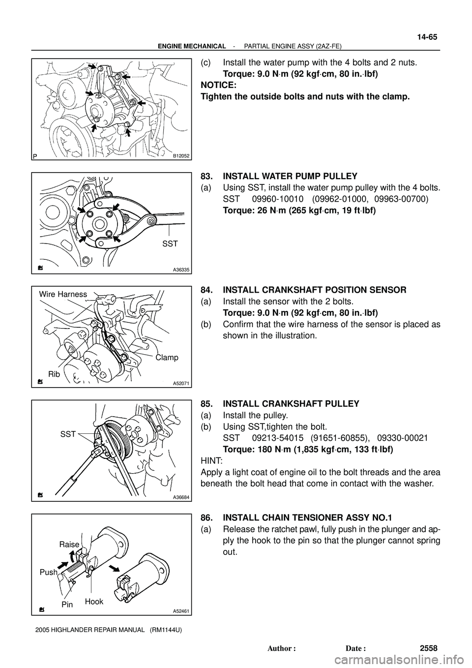
(c) Install the water pump with the 4 bolts and 2 nuts.
Torque: 9.0 NVm (92 kgfVcm, 80 in.Vlbf)
NOTICE:
Tighten the outside bolts and nuts with the clamp.
83. INSTALL WATER PUMP PULLEY
(a) Using SST, install the water pump pulley with the 4 bolts.
SST 09960-10010 (09962-01000, 09963-00700)
Torque: 26 NVm (265 kgfVcm, 19 ftVlbf)
84. INSTALL CRANKSHAFT POSITION SENSOR
(a) Install the sensor with the 2 bolts.
Torque: 9.0 NVm (92 kgfVcm, 80 in.Vlbf)
(b) Confirm that the wire harness of the sensor is placed as
shown in the illustration.
85. INSTALL CRANKSHAFT PULLEY
(a) Install the pulley.
(b) Using SST,tighten the bolt.
SST 09213-54015 (91651-60855), 09330-00021
Torque: 180 NVm (1,835 kgfVcm, 133 ftVlbf)
HINT:
Apply a light coat of engine oil to the bolt threads and the area
beneath the bolt head that come in contact with the washer.
86. INSTALL CHAIN TENSIONER ASSY NO.1
(a) Release the ratchet pawl, fully push in the plunger and ap-
ply the hook to the pin so that the plunger cannot spring
out.
100MI-01
A81214
- ENGINE CONTROL SYSTEMACCELERATOR PEDAL ROD ASSY (2AZ-FE)
10-1 1
2369 Author�: Date�:
2005 HIGHLANDER REPAIR MANUAL (RM1144U)
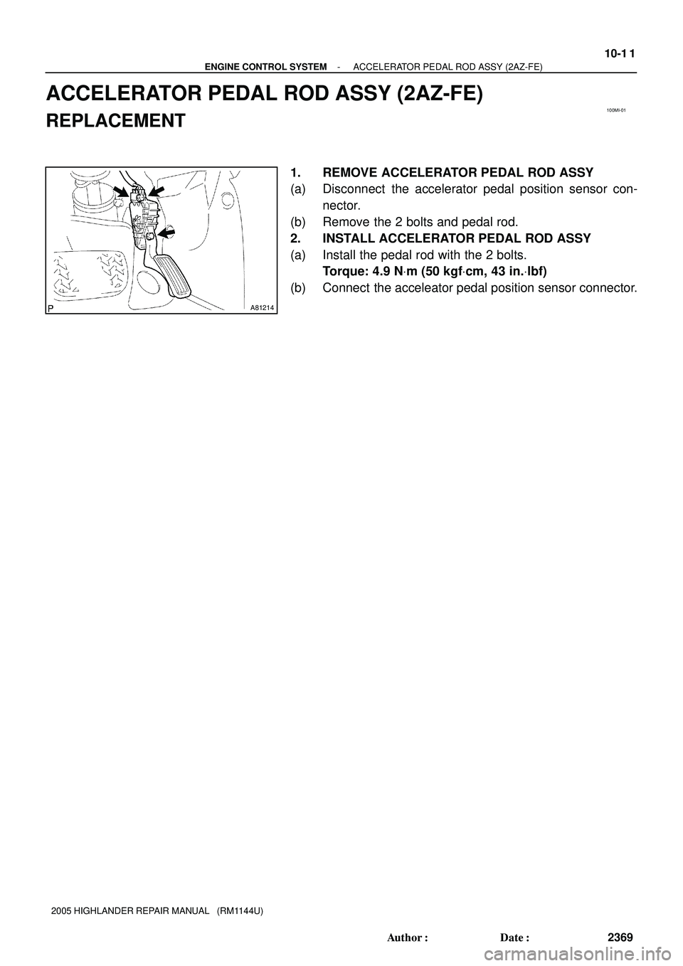
ACCELERATOR PEDAL ROD ASSY (2AZ-FE)
REPLACEMENT
1. REMOVE ACCELERATOR PEDAL ROD ASSY
(a) Disconnect the accelerator pedal position sensor con-
nector.
(b) Remove the 2 bolts and pedal rod.
2. INSTALL ACCELERATOR PEDAL ROD ASSY
(a) Install the pedal rod with the 2 bolts.
Torque: 4.9 NVm (50 kgfVcm, 43 in.Vlbf)
(b) Connect the acceleator pedal position sensor connector.