Page 657 of 2572
2005 HIGHLANDER (EWD592U)
298
Automatic Air Conditioning
10A
HEATER
1K 13
IK4 1
25 413A A1G 8
3A 4
3J 7
IL2 2
A 7A2
IH1 2IL25
IH1 1
21
IH1 3
IAM B 14AMH
B 13AMC
B 12SG- 1
B 11S5- 1
IJ1 1IJ12IJ13IJ14IJ15B 10TP
IJ1 6B 5TE
A14
B
GR
P
O
SB
LG Y- G
Y
LG- R LG- R
P- L P- L
O O
5421 2
4
B 6A
3
B- Y
Y
B Y
BRJ 5
BR O
HR IG+H 9
LG W P- LB
W- B
YY
W
50A HTR
7F 7
4L 74H 7
IC
W- B
I12 W- B
B
I14
1 2
E12VMSI
G- Y
A 17BLW
1 GND
W- BB
3
+B
RB 7BBW- B
ILL+ ILL- ILL- ACC IG BLK STX ILL+ +B 16 12 13 1 2 15 14 6 7
LG- R
LG- R Control Panel
M From Power Source System (
See Page 62)
A10(
A)
, A11(
B)
A/C Control Assembly
Air Mix Control Servo Motor
Blower Motor
Blower Motor
Control
Evapor ator Temp. Sensor
Fusible
Link Block
Heater
Relay
Junction
Connector
Page 663 of 2572
2005 HIGHLANDER (EWD592U)
304
Manual Air Conditioning
50A HTR
7F 7
10A
HEATER
1K 13 1G 8
A A
A
25 413 IK4 1
I 6
OO
A 7
IA 8
423
1 456
II1 5 II1 4 II1 2
I13 1 2II1 1IG1 1
IC 4L 74H 7IG1 21
II16
3F 133J 6
IB 3J 10A 11 3J 73A 4
1K 21G 10
3I 113A 13
A 2A12 A13 IC3 57. 5A
ECU- B
2A 47. 5A
RAD
NO. 2
1K 3
Y
W- B W- B B B W- BWY
BR W BR
GR VBY
B
W- L
VB- Y
BR B W
O B- Y BW- B W- B
R- B
GR
W- B
W- BR
L
BR
W- BY
H 9 J 5
HR IG+ +B ACC
GND
B
LO
HI M2 M1 E
W- B W- B
B 8B 5
B 6
2IL2
MFrom Power Source System (
See Page 62)
A10(
A)
, A11(
B)
A/C Control Assembly
Blower Control SW
Blower Motor
Blower Resistor
Fusible Link
Block
Heater Relay Junction
Connector
Page 667 of 2572

308
Manual Air Conditioning
1. Heater Blower Motor Operation
Current is applied at all times through the HTR fuse to TERMINAL 1 of the HEATER relay.
When the ignition SW is t")
2005 HIGHLANDER (EWD592U)
308
Manual Air Conditioning
1. Heater Blower Motor Operation
Current is applied at all times through the HTR fuse to TERMINAL 1 of the HEATER relay.
When the ignition SW is turned on, current flows through the HEATER fuse to TERMINAL 3 of the HEATER relay to
TERMINAL 5 to TERMINAL 8 of the blower control SW.
*Low speed operation
When the blower SW is moved to LO position, the current to TERMINAL 8 of the blower control SW flows to TERMINAL
1 to GROUND, causing the HEATER relay is turned on. This causes the current to flow from the HTR fuse to TERMINAL
1 of the HEATER relay to TERMINAL 2 to TERMINAL 2 of the blower motor to TERMINAL 1 to TERMINAL 1 of the
blower resistor to TERMINAL 4 to GROUND, causing the blower motor to rotate at low speed.
*Medium speed operation (Operation at M1, M2)
When the blower SW is moved to M1 position, the current to TERMINAL 8 of the blower control SW flows to TERMINAL
1 to GROUND, turns the HEATER relay on. This causes the current to flow from the HTR fuse to TERMINAL 1 of the
HEATER relay to TERMINAL 2 to TERMINAL 2 of the blower motor to TERMINAL 1 to TERMINAL 1 of the blower
resistor to TERMINAL 2 to TERMINAL 6 of the blower control SW to TERMINAL 1 to GROUND. At this time, the blower
resistance of the blower resistor is less than at low speed, so the blower motor rotates at medium low speed.
When the blower control SW is moved to M2 position, current flowing through the motor flows from TERMINAL 1 of the
blower resistor to TERMINAL 3 to TERMINAL 5 of the blower control SW to TERMINAL 1 to GROUND. At this time,
resistance of the blower resistor is less than at M1 position, so the blower motor rotates at medium high speed.
*High speed operation
When the blower SW is moved to HI position, the current flows to TERMINAL 8 of the blower control SW to TERMINAL
1 to GROUND and turns the HEATER relay on.
This causes the current to flow from the HTR fuse to TERMINAL 1 of the HEATER relay to TERMINAL 2 to TERMINAL 2
of the blower motor to TERMINAL 1 to TERMINAL 4 of the blower control SW to TERMINAL 1 to GROUND, causing the
blower motor to rotate at high speed.
2. Air Conditioning Operation
If the A/C control SW is turned on when the blower SW is set to on, A/C operation starts. However, when the mode SW is at
DEF or FOOT/DEF position, forcibly the air intake is set to FRESH mode and the A/C operates.
A3 Pressure SW
1-4 : Open with the pressure less than 2.0 kgf/cm2 (28 psi, 196 kpa) or above 32 kgf/cm2 (455 psi, 3138 kpa)
A10 (A) A/C Control Assembly
(A) 11-Ground : Always continuity
(A) 2-Ground : Approx. 12 volts with the ignition SW at ON position
(A)12-Ground : Always approx. 12 volts
(A)13-Ground : Approx. 12 volts with the ignitino SW at ACC or ON position
B8 Blower Resistor
1-3 : Approx. 0.22 W
1-2 : Approx. 0.69 W
1-4 : Approx. 1.69 W
B5 Blower Control SW
8-1 : Continuity with the blower SW at LO, M1, M2 or HI position
6-1 : Continuity with the blower SW at M1 position
5-1 : Continuity with the blower SW at M2 position
4-1 : Continuity with the blower SW at HI position
System Outline
Service Hints
Page 671 of 2572
2005 HIGHLANDER (EWD592U)
312
Rear Heater
15A
RR HTR
210A
HEATER
2 1
1G 81K13
IK2 2
IA2 11
BH1 9IO118
IR113
B- R O L L
Y Y
B
B Y Y
BL PW
J 5
R25
R26 A A
51
32
3 46
BB BF W- B W- B
W- B
W- BW- B
A
A
AA
R24
IR1 17
GR BR
8 6 5 M
1 2
3IND RLY
E
HI COM DUMMY E
OFF
LO
HI 4
W- B
W- B A
R27
J19
From Power Source System (
See Page 62)
Junction
Connector
Junction
ConnectorRear Heater
Main SW
Rear Heater Blower
Motor
Rear Heater Blower SW
Rear Heater
Relay
Page 1477 of 2572
I40780
A/C Amplifier Assy
A10 HR O
1H9
Heater
Relay
35
G7
2 J5
J/C
HEATER 10A
AM17
IG1
1
28
6 I15
Ignition SW
A
W
FL MAIN
BatteryInstrument Panel J/B
IL2 BR Y
Y
A 1G
1A 1C 1C
1 4 2
W
1
7
F7
Fusible Link BlockALTHEATER 50A 2B
B-YW
1 IK442
4H4L7 7
W-B
W-B
IC Passenger Side J/BFrom Blower
Motor AM1B
- DIAGNOSTICSAIR CONDITIONING SYSTEM
05-1 187
1377 Author�: Date�:
2005 HIGHLANDER REPAIR MANUAL (RM1144U)
HEATER RELAY CIRCUIT
CIRCUIT DESCRIPTION
The heater relay is switched on by signals from the A/C amplifier assy. It supplies power to the blower motor.
WIRING DIAGRAM
05IU7-03
Page 1478 of 2572

INSPECTION P")
Z19533
5
4 3
12125
4 3
I30331HR
A/C Amplifier Connector
Wire Harness View:
A10
05-1 188
- DIAGNOSTICSAIR CONDITIONING SYSTEM
1378 Author�: Date�:
2005 HIGHLANDER REPAIR MANUAL (RM1144U)
INSPECTION PROCEDURE
1 CHECK FUSE(15 A HEATER, 50 A HEATER, AM1 FUSES)
(a) Remove the 15 A HEATER and AM1 fuses from the instrument panel J/B.
(b) Remove the 50 A HEATER fuse from fusible link block.
(c) Check that the continuity exists in 15 A HEATER and 50 A HEATER, AM1 fuses.
NG REPLACE FUSE
OK
2 INSPECT HEATER BLOWER MOTOR RELAY ASSY
(a) Check that the continuity exists between each pair of ter-
minals of heater blower motor relay assy, as shown in the
chart.
Tester connectionConditionSpecified condition
2 - 1Always10 kW or higher
2 - 4AlwaysBelow 1.0 W
(b) Check continuity between each pair of terminals, as
shown the chart.
Tester connectionConditionSpecified condition
2 - 1When battery voltage ap-
plied to terminals 3 and 5Below 1.0 W
2 - 4When battery voltage ap-
plied to terminals 3 and 510 kW or higher
NG REPLACE HEATER BLOWER MOTOR RELAY
ASSY
OK
3 INSPECT AIRCONDITIONER AMPLIFIER ASSY(HR)
(a) Remove the A/C amplifier assy with connectors still con-
nected.
(b) Measure the voltage according to the value(s) in the table
below.
Standard:
Tester connectionConditionSpecified condition
A10-7 (HR) -
Body groundIgnition switch OFF0 V
A10-7 (HR) -
Body groundIgnition switch ON
Blower switch ONBelow 1.0 V
A10-7 (HR) -
Body groundIgnition switch ON
Blower switch OFF10 to 14 V
OK PROCEED TO NEXT CIRCUIT INSPECTION
SHOWN IN PROBLEM SYMPTOMS TABLE
NG
Page 1484 of 2572
Duty Ratio =A + BA
x 100 (%)
ON
OFFA
B
1 cycle
Blower Level
0
Si duty (%)
LO M1 M2HI
2941
6789
53 M3
I30519
IL2 1
W
IH1BLW A1017
LGA/C Amplifier Assy
B7
Blower Motor Control
5
P-L
2
1 4
3SI
GND VM
+B 1
2
R
B B
B 2
B
IH1W-B
IH1 3
W-B
IA From
H9
Heater
RelayB6
Blower Motor
- DIAGNOSTICSAIR CONDITIONING SYSTEM
05-1 181
1371 Author�: Date�:
2005 HIGHLANDER REPAIR MANUAL (RM1144U)
BLOWER MOTOR CIRCUIT
CIRCUIT DESCRIPTION
The blower motor is operated by signals from the A/C amplifier
assy. Blower motor speed signals are transmitted by changes
in the Duty Ratio.
Duty Ratio
The duty ratio is the ratio of the period of continuity in one cycle.
For example, if A is the period of continuity in one cycle, B is the
period of non-continuity.
WIRING DIAGRAM
05IU6-01
Page 1485 of 2572
I41004
B7
A10
SI
A/C Amplifier Connector
Wire Harness View: Blower Motor Controller Connector
Front View:
05-1 182
- DIAGNOSTICSAIR CONDITIONING SYSTEM
1372 Author�: Date�:
2005 HIGHLANDER REPAIR MANUAL (RM1144U)
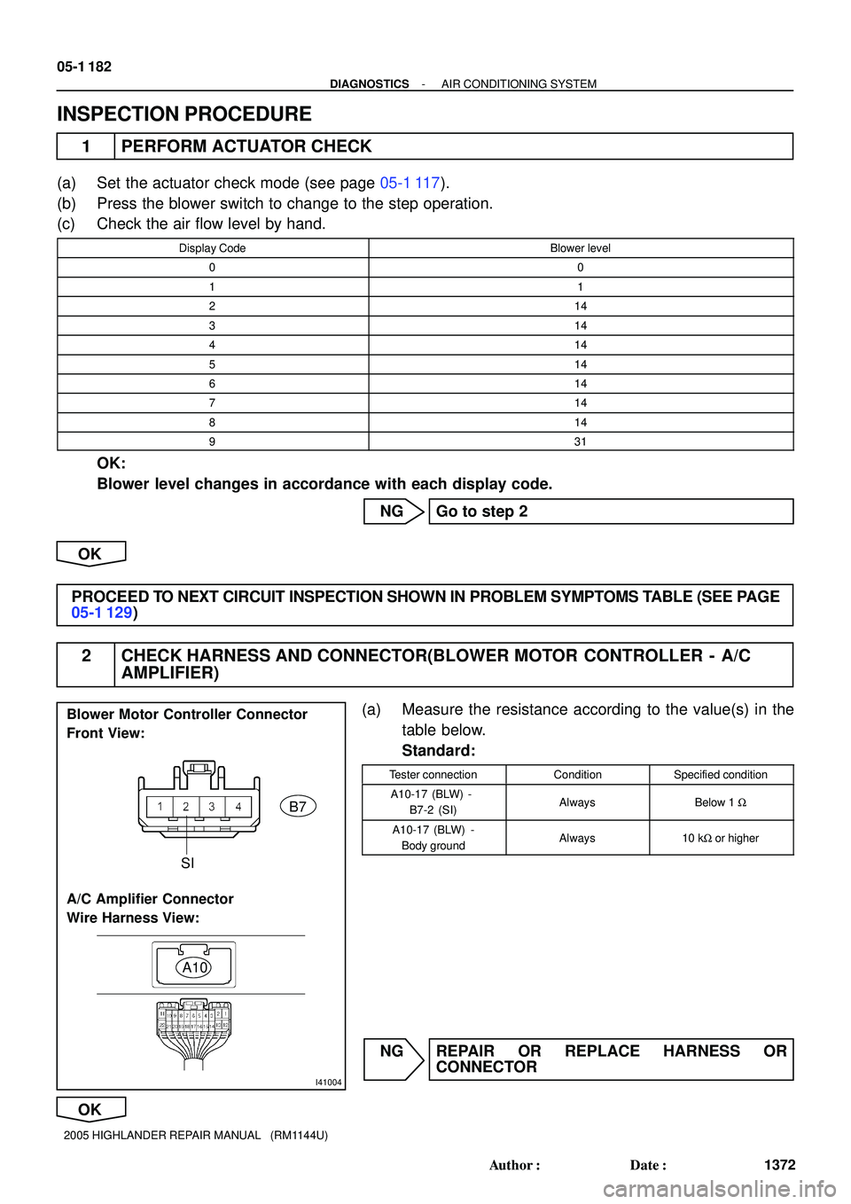
INSPECTION PROCEDURE
1 PERFORM ACTUATOR CHECK
(a) Set the actuator check mode (see page 05-1 117).
(b) Press the blower switch to change to the step operation.
(c) Check the air flow level by hand.
Display CodeBlower level
00
11
214
314
414
514
614
714
814
931
OK:
Blower level changes in accordance with each display code.
NG Go to step 2
OK
PROCEED TO NEXT CIRCUIT INSPECTION SHOWN IN PROBLEM SYMPTOMS TABLE (SEE PAGE
05-1 129)
2 CHECK HARNESS AND CONNECTOR(BLOWER MOTOR CONTROLLER - A/C
AMPLIFIER)
(a) Measure the resistance according to the value(s) in the
table below.
Standard:
Tester connectionConditionSpecified condition
A10-17 (BLW) -
B7-2 (SI)AlwaysBelow 1 W
A10-17 (BLW) -
Body groundAlways10 kW or higher
NG REPAIR OR REPLACE HARNESS OR
CONNECTOR
OK

298
Automatic Air Conditioning
10A
HEATER
1K 13
IK4 1
25 413A A1G 8
3A 4
3J 7
IL2 2
A 7A2
IH1 2IL25
IH1 1
21
IH1 3
IAM B 14AMH
B 13AMC
B 12SG- 1
B 11S5- 1
IJ1 1IJ12IJ13IJ14IJ")

304
Manual Air Conditioning
50A HTR
7F 7
10A
HEATER
1K 13 1G 8
A A
A
25 413 IK4 1
I 6
OO
A 7
IA 8
423
1 456
II1 5 II1 4 II1 2
I13 1 2II1 1IG1 1
IC 4L 74H 7IG1 21
II16
3F 133J")

312
Rear Heater
15A
RR HTR
210A
HEATER
2 1
1G 81K13
IK2 2
IA2 11
BH1 9IO118
IR113
B- R O L L
Y Y
B
B Y Y
BL PW
J 5
R25
R26 A A
51
32
3 46
BB BF W- B W- B
W- B
W- BW- B
A
A
AA")


ON
OFFA
B
1 cycle
Blower Level
0
Si duty (%)
LO M1 M2HI
2941
6789
53 M3
I30519
IL2 1
W
IH1BLW A1017
LGA/C Amplifier Assy
B7
Blower Motor Control
5
P-L
2
1 4
3SI
GND VM
+B")