Page 1486 of 2572
E69146
B7
GND
Blower Motor Controller Connector
Front View:
E68546E69147
+- Blower w/ Fan Motor Sub-assy
Front View:
B6
- DIAGNOSTICSAIR CONDITIONING SYSTEM
05-1 183
1373 Author�: Date�:
2005 HIGHLANDER REPAIR MANUAL (RM1144U)
3 CHECK HARNESS AND CONNECTOR(BLOWER MOTOR CONTROLLER - BODY
GROUND)
(a) Measure the resistance according to the value(s) in the
table below.
Standard:
Tester connectionConditionSpecified condition
B7-1 (GND) -
Body groundAlwaysBelow 1 W
NG REPAIR OR REPLACE HARNESS OR
CONNECTOR
OK
4 INSPECT COOLING UNIT MOTOR SUB-ASSY W/FAN
(a) Remove the blower w/ fan motor sub-assy.
(b) Connect positive (+) lead to terminal 2 of the blower motor
connector and negative (-) lead to terminal 1.
Standard: Blower motor operates smoothly.
NG REPLACE COOLING UNIT MOTOR SUB-ASSY
W/FAN
OK
Page 1488 of 2572
I36240
B7
B6
VM
Blower Motor Connector Front View: Blower Motor Controller Connector
Front View:
- DIAGNOSTICSAIR CONDITIONING SYSTEM
05-1 185
1375 Author�: Date�:
2005 HIGHLANDER REPAIR MANUAL (RM1144U)
6 CHECK HARNESS AND CONNECTOR(BLOWER MOTOR CONTROLLER -
BLOWER MOTOR)
(a) Measure the resistance according to the value(s) in the
table below.
Standard:
Tester connectionConditionSpecified condition
B7-4 (VM) - B6-1AlwaysBelow 1 W
B7-4 (VM) -
Body groundAlways10 kW or higher
NG REPAIR OR REPLACE HARNESS OR
CONNECTOR
OK
Page 1489 of 2572
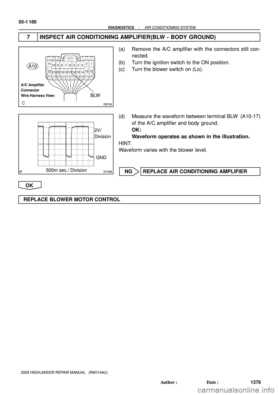
I38764
A10
BLW
A/C Amplifier
Connector
Wire Harness View:
I31456
GND 2V/
Division
500m sec./ Division
05-1 186
- DIAGNOSTICSAIR CONDITIONING SYSTEM
1376 Author�: Date�:
2005 HIGHLANDER REPAIR MANUAL (RM1144U)
7 INSPECT AIR CONDITIONING AMPLIFIER(BLW - BODY GROUND)
(a) Remove the A/C amplifier with the connectors still con-
nected.
(b) Turn the ignition switch to the ON position.
(c) Turn the blower switch on (Lo).
(d) Measure the waveform between terminal BLW (A10-17)
of the A/C amplifier and body ground.
OK:
Waveform operates as shown in the illustration.
HINT:
Waveform varies with the blower level.
NG REPLACE AIR CONDITIONING AMPLIFIER
OK
REPLACE BLOWER MOTOR CONTROL
Page 1607 of 2572

05-1674
- DIAGNOSTICSAUDIO SYSTEM
1864 Author�: Date�:
2005 HIGHLANDER REPAIR MANUAL (RM1144U)
NOISE OCCURS
INSPECTION PROCEDURE
1 CHECK OF SPEAKER INSTALLATION
(a) Check the speaker installation condition.
(1) Check that each speaker is securely installed.
OK: Malfunction disappears.
HINT:
The radio is equipped with a noise prevention system that blocks only excessively loud noise. If loud noise
occurs, check whether or not the ground on the antenna installation part and the proper noise-prevention
equipment are all installed, and whether or not there is improper wiring.
Condition in which noise occursNoise type
Depressing the acceleration pedal increases the noise, and stopping the
engine stops the noise immediately.Alternator noise
Noise occurs during A/C or the heater operation.Blower motor noise
Rapid acceleration during the drive on an unpaved road or after the ignition
switch is turned on makes noise.Fuel pump noise
Pressing and then releasing the horn switch, and keeping pressing the horn
switch makes noise.Horn noise
Quiet noise is heard while the engine is running, but stops with the engine.Ignition noise
Noise occurs in turn with the blink of the turn signal flash.Flasher noise
Noise occurs during window washer operation.Washer noise
Noise occurs while the engine is running, and it continues even after the en-
gine is stopped.Water temperature sensor noise
Noise occurs during wiper operation.Wiper noise
Noise occurs when the brake pedal is depressed.Stop light switch noise
OthersStatic electricity on the vehicle
HINT:
�Identify the condition in which the noise occurs, and check the noise filter on the related part.
�Make sure first that there is no noise from outside. Failing to do so makes the noise occurrence source
detection difficult and leads to misdiagnosis.
�The noise should be removed in descending order of loudness.
NG INSTALL IT PROPERLY
OK
IDENTIFICATION OF NOISE SOURCE
055M1-10
Page 2154 of 2572
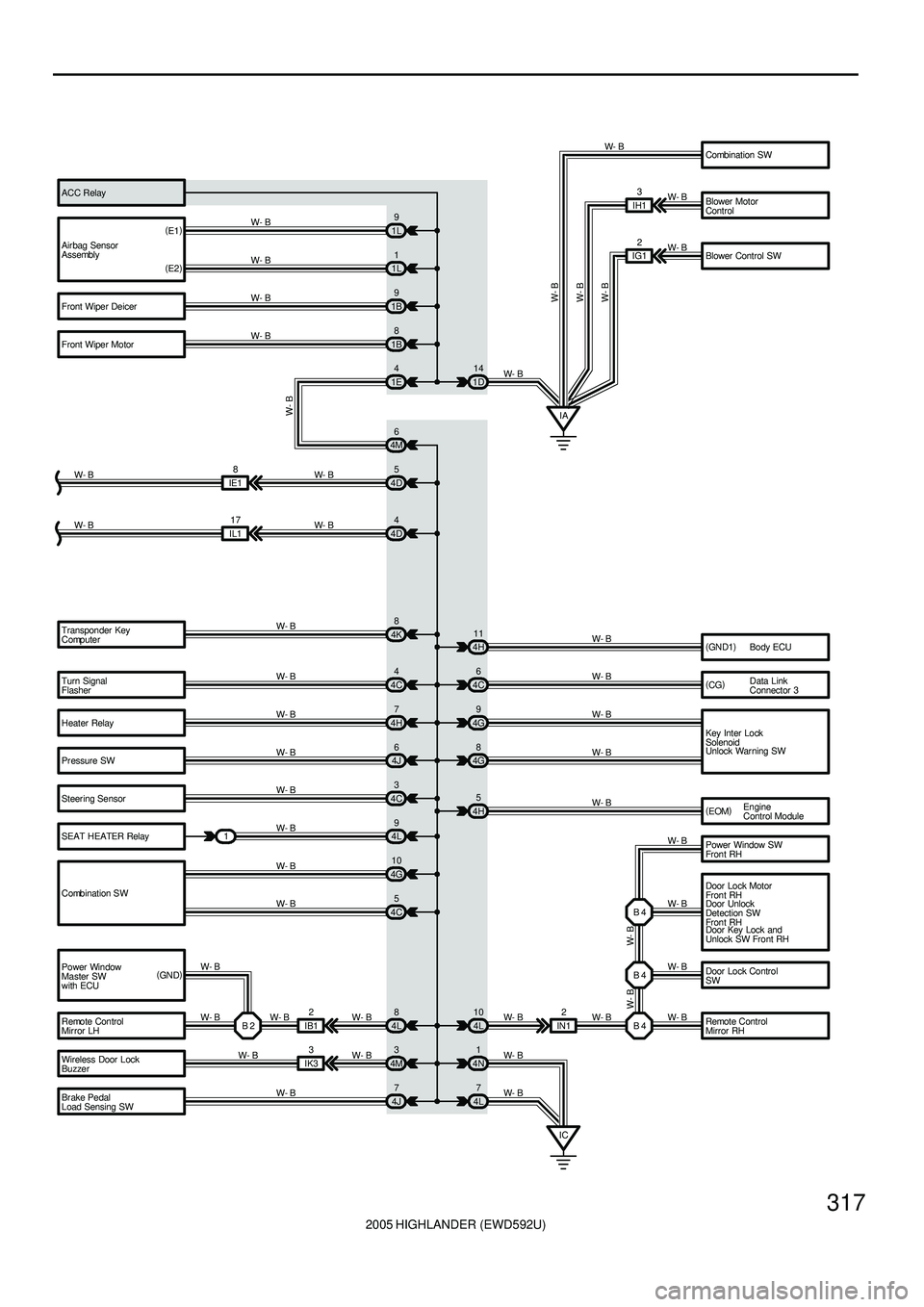
2005 HIGHLANDER (EWD592U)
317
Turn Signal
Flasher
Heater Relay
Pr essure SW
Steer ing Sensor
SEAT HEATER Relay
Combination SW
Power Window
Master SW
with ECU
Remote Control
Mir ror LH Transponder Key
Computer
Body ECU
Data Link
Connector 3
Key Inter Lock
Solenoid
Remote Control
Mirror RH Door Lock Control
SW Power Window SW
Fron t RH
Door Unlock
Detection SW
Fron t RH
Wireless Door Lock
Buzzer
Br ake Pedal
Load Sensing SW4C44H11
4C6
4G9
4G8 4H7
4J6
4C3
4L9
4G10
4C5 W- B
W- B
W- B
W- B
W- B
W- B
W- B
W- BW- B
W- BW- B
W- B
W- B
B 2 I B 12
W- B
4L8
W- B
IK33
4M3
W- B
4J7 W- B
W- B4L 10 2
IN1 W- B
B 4W- B B 4 B 4
W- BW- B W- B
W- B
4N1
4L7
IC W- B
W- B(
GN D1)
(
CG)
4H5
W- B
W- B W- B
4D4
IL117
W- B W- B
4K8
W- B4D5
IE18
W- B W- B Air bag Sensor
Assembly
Front Wiper Deicer
Front Wiper Motor(
E1)
(
E2)1L9
1L1
1B9
1B8
1D14 W- B
W- B
W- B
W- B
W- B
W- B
W- B
W- B
Combination SW
Blower Motor
Control
Blower Control SW ACC Relay
IG12 W- B
W- B
W- B
IA 1E4
4M6
W- B
IH13
(
GN D)Engine
Control Module (
EOM)
1Unlock Warning SW
Door Lock Motor
Fron t RH
Door Key Lock and
Unlock SW Front RH
Page 2155 of 2572
2005 HIGHLANDER (EWD592U)
318
I GROUND POINT
Door Lock Motor
Rear RH
Power Window SW
Rear RH BC113
BC112
W- BW- B
BBW- B
W- B
Seat Heater SW RH BM11
W- BW- B
Stereo Power
Amplifier Wireless Door
Lock ECU Yaw Rate Sensor Char coal Canister
Assembly Rear Heater Blower
Motor Rear Heater Relay Rear Heater
Blower SWA
A
A
A
A
A
A
A BJ115 W- B
W- B
W- B
W- B
W- B W- B
W- B
W- B
W- B
BF
W- B
ARear Seat
Entertainment
ECU
(
SELD) (
GND)
J19
Occupant
Classification
ECU BL13
W- B W- B
W- B
W- B C
C
C
W- B
J18
C A
W- B
B A B A
A A Power Seat
Control SW
(
Front Passenger' s
Seat Contr ol)W- B
W- B W- B
(
*4)
(
*5) (
*5) (
*4) (
*4)* 4 : w/ Power Seat(
Front Passenger' s Seat)
* 5 : w/o Power Seat(
Front Passenger' s Seat)
(
E)(
GND) Door Unlock
Detection SW
Rear RH J23(
A)
, J24(
B)
Junction
Connector Junction
Connector
Junction Connector
Page 2165 of 2572
2005 HIGHLANDER (EWD592U)
8
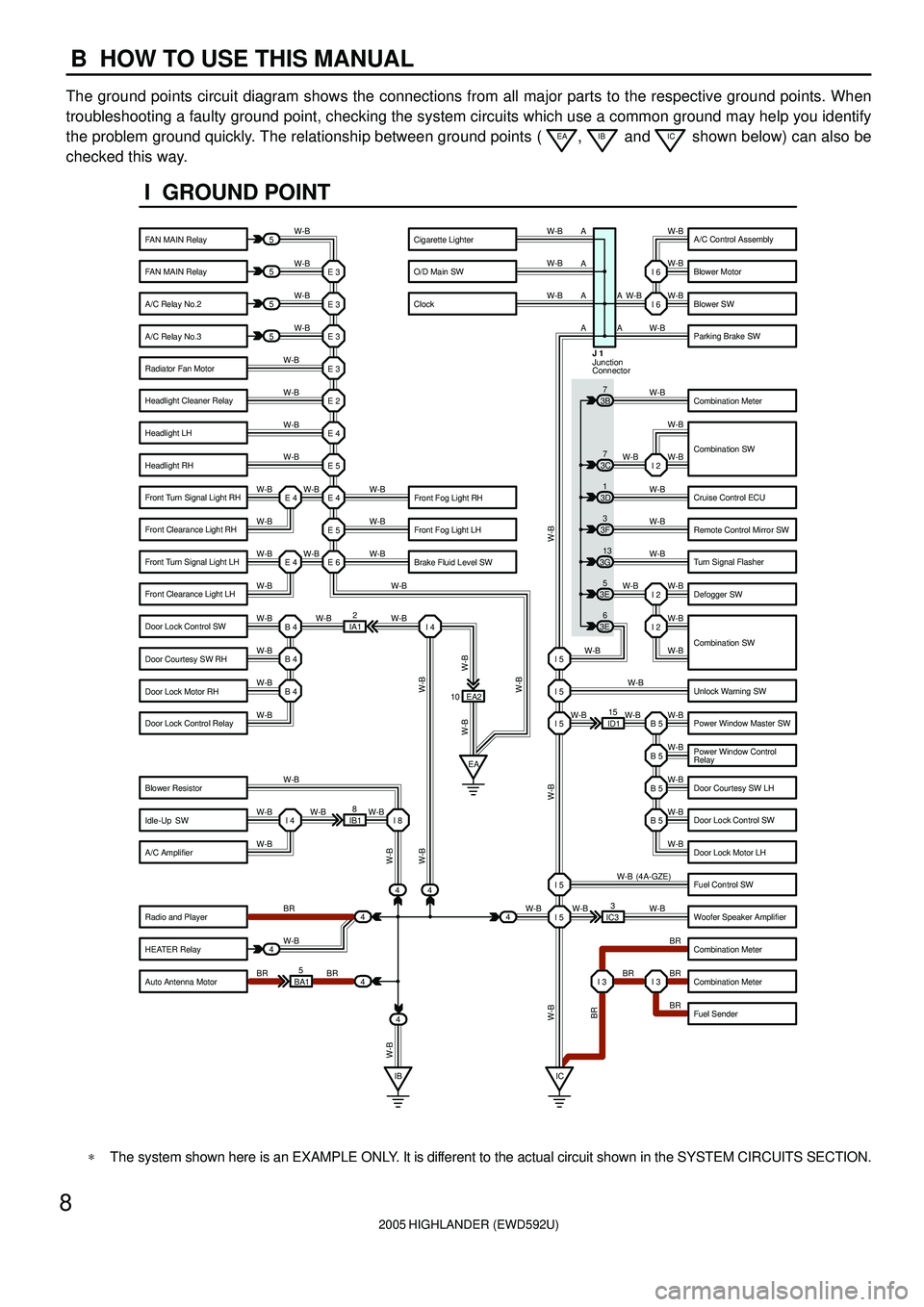
B HOW TO USE THIS MANUAL
The ground points circuit diagram shows the connections from all major parts to the respective ground points. When
troubleshooting a faulty ground point, checking the system circuits which use a common ground may help you identify
the problem ground quickly. The relationship between ground points (
EA, IB and IC shown below) can also be
checked this way.
5
5
5
5
4
44
4
4 BA15IB18EA2
ID115
IC33 IA12 E 3
W-BW-B W-B W-B W-B
W-B
W-B
W-B
W-B W-B
W-B
W-B W-B
W-B
W-B W-B W-BW-B W-B W-B W-B
W-B
W-B
W-B
W-B W-B W-B
W-B
BR
W-B
BR BRW-BW-B W-B
W-B
W-B
W-B
W-B W-B W-B
W-B
W-B W-B
W-B
W-B
BR W-B
BR BR
BR W-B (4A-GZE)
W-B W-BI 2
I 2
B 5 I 5 I 5 I 5
B 5
B 5
B 5
I 5
I 5
I 3 I 3 E 3
E 3
E 3
E 2
E 4
E 5
E 4
E 5
E 6 E 4 E 4
B 4
EA I 4
B 4
B 4
I 4 I 8
IB IC 443E5
3E6 3G13 3F3 3D1 3B7W-B
W-B
W-B W-B W-B
W-B
W-B
W-B
W-B
W-B
W-B
W-B
W-B
W-B W-BI 6
I 6
I 2 3C7
10A A A A
A
A
Junction
Connector J 1
W-B
W-B
W-B W-B
BR W-B W-B
W-B
W-B W-B
W-B
I GROUND POINT
FAN MAIN Relay
FAN MAIN Relay
A/C Relay No.2
A/C Relay No.3
Radiator Fan Motor
Headlight Cleaner Relay
Headlight LH
Headlight RH
Front Fog Light LH
Brake Fluid Level SW Front Fog Light RH Front Turn Signal Light RH
Front Clearance Light RH
Front Turn Signal Light LH
Front Clearance Light LH
Door Lock Control SW
Door Courtesy SW RH
Door Lock Motor RH
Door Lock Control Relay
Blower Resistor
Idle-Up SW
A/C Amplifier
Radio and Player
HEATER Relay
Auto Antenna MotorA/C Control Assembly
Blower Motor
Blower SW
Parking Brake SW
Combination Meter
Combination SW
Cruise Control ECU
Remote Control Mirror SW
Turn Signal Flasher
Defogger SW
Unlock Warning SW
Power Window Master SW
Power Window Control
Relay
Door Courtesy SW LH
Door Lock Control SW
Door Lock Motor LH
Fuel Control SW
Woofer Speaker Amplifier
Combination Meter
Combination Meter
Fuel Sender Cigarette Lighter
O/D Main SW
Clock
Combination SW
*The system shown here is an EXAMPLE ONLY. It is different to the actual circuit shown in the SYSTEM CIRCUITS SECTION.
Page 2321 of 2572

2005 HIGHLANDER (EWD592U)
M OVERALL ELECTRICAL WIRING DIAGRAM
1
234
34 HIGHLANDER(
Cont. next page)
Power SourceA ir C onditioning (
Automatic A/C)
73
1B- YW50A
HTR
140A
ALT2I 1
40A AM17. 5A
ECU- B
2ACC
IG1 AM1 4
1C
6
1A 12A 4
10 A HEAT ER
71C
1K 13 1G82 1
5 3
4 1IK4
A A
5IL2 4H 7
4L 7
IC Right Cowl Side Panel1IH1
3IH1
IALeft Cowl Side Panel M 21 2IH117 A3A 4
3J 71G 10
1K 2 5IC3
7A 2A 12A4B2 1
16 B 15 B 3 B
1 IJ1 2 I J1 3 I J1 4 IJ1 5 IJ1 6 IJ1
1 2
M 14 B 13 B 12 B 11 B 10 B 5 B D. C. C
32
54213
41 2
B WW- B W- BBBRW- B Y- GY
B GRP O SB LG G- Y
LG- R LG- RP- LO WY
L W
W
BR
O BR Y
WB
WG
W- L
W- B
LG
LG- R
B BR
B- Y
Y
B
WP-L
W- B B
LG- R BLW AMH AMC SG- 1 S5- 1 TP TEHR IG +B S5- 3 TS SG- 3 TR
WFL MAIN
3. 0W
Bat teryYA
YA
W- L
B
Y
2 1
1 2
VM SI
GN D +B2IL2 ST1
13 A3A 13
3I 111K 31C 2 3
LL
GR VACC
7. 5A
RAD NO. 2
F 7I15
H 9 A12 R 6
J 5
A10(
A)
, A11(
B)
B 7
B 6A14
E1 2
A/C Control Assembly
A/C Solar Sensor
Air Mix Control Servo Motor
Blower MotorBlower Motor Cont rol
Evaporator Temp.
Se nso r
Fusible Link Block
Heater Relay
Ignition SW
Junction
Connec tor
Room Temp. Sensor