Page 969 of 2572
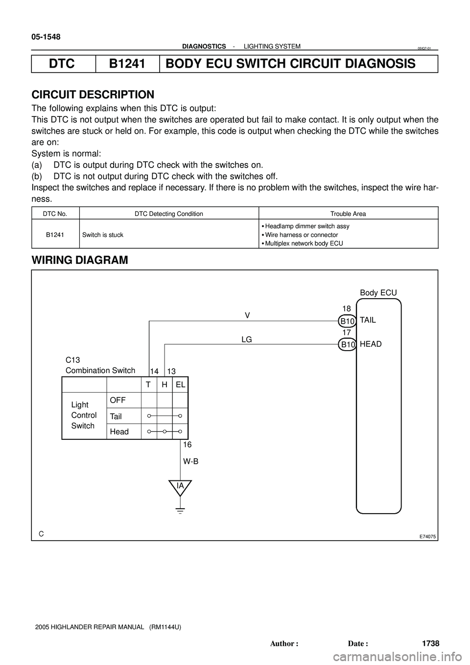
E74075
Body ECU
C13
Combination Switch
Light
Control
SwitchTAIL
HEAD
OFF
Tail
HeadV
LG18
B10
17
B10
14 13
THEL
IA16
W-B 05-1548
- DIAGNOSTICSLIGHTING SYSTEM
1738 Author�: Date�:
2005 HIGHLANDER REPAIR MANUAL (RM1144U)
DTC B1241 BODY ECU SWITCH CIRCUIT DIAGNOSIS
CIRCUIT DESCRIPTION
The following explains when this DTC is output:
This DTC is not output when the switches are operated but fail to make contact. It is only output when the
switches are stuck or held on. For example, this code is output when checking the DTC while the switches
are on:
System is normal:
(a) DTC is output during DTC check with the switches on.
(b) DTC is not output during DTC check with the switches off.
Inspect the switches and replace if necessary. If there is no problem with the switches, inspect the wire har-
ness.
DTC No.DTC Detecting ConditionTrouble Area
B1241Switch is stuck
�Headlamp dimmer switch assy
�Wire harness or connector
�Multiplex network body ECU
WIRING DIAGRAM
05IQ7-01
Page 970 of 2572

INSPECTION PROCEDURE
1 READ VALUE OF HAND-HELD TESTER
(a) Connect")
E11948
Connector Front View:
C13
- DIAGNOSTICSLIGHTING SYSTEM
05-1549
1739 Author�: Date�:
2005 HIGHLANDER REPAIR MANUAL (RM1144U)
INSPECTION PROCEDURE
1 READ VALUE OF HAND-HELD TESTER
(a) Connect the hand-held tester to the DLC3.
(b) Turn the ignition switch to the ON position and turn the hand-held tester main switch on.
(c) Select the item below in the DATA LIST and read the display on hand-held tester.
BODY NO.1 (MULTIPLEX NETWORK BODY ECU):
ItemMeasurement Item/
Display (Range)Normal ConditionDiagnostic Note
HEAD LIGHT SWHeadlight control
SW signal/ ON or OFFON: Light control switch is in HEAD position
OFF: Light control switch is in except HEAD position-
TAIL LIGHT SWTail light SW signal/
ON or OFFON: Light control switch is in TAIL position
OFF: Light control switch is in except TAIL position-
OK: Condition sign can be displayed.
NG Go to step 2
OK
REPLACE MULTIPLEX NETWORK BODY ECU
2 INSPECT HEADLAMP DIMMER SWITCH ASSY
(a) Inspect light control switch.
(1) Measure the resistance according to the value(s) in
the table below.
Standard:
Tester connectionConditionSpecified condition
14 - 16TAILBelow 1 W
13 - 16
14 - 16HEADBelow 1 W
NG REPLACE HEADLAMP DIMMER SWITCH ASSY
(SEE PAGE 65-25)
OK
Page 971 of 2572
E11948
Headlamp Dimmer Switch Connector
Front View:
C13
E74263
B10
B10-17
B10-18 Multiplex Network Body ECU
Connector Front View:
05-1550
- DIAGNOSTICSLIGHTING SYSTEM
1740 Author�: Date�:
2005 HIGHLANDER REPAIR MANUAL (RM1144U)
3 CHECK HARNESS AND CONNECTOR(HEADLAMP DIMMER SWITCH ASSY -
MULTIPLEX NETWORK BODY ECU)
(a) Disconnect the headlamp dimmer switch assy connector
and B10 connector from the multiplex network body ECU.
(b) Measure the resistance according to the value(s) in the
table below.
Standard:
Tester connectionConditionSpecified condition
C13-13 - B10-17AlwaysBelow 1 W
C13-14 - B10-18AlwaysBelow 1 W
B10-17 - Body groundAlways10 kW or higher
B10-18 - Body groundAlways10 kW or higher
C13-16 - Body groundAlwaysBelow 1 W
NG REPAIR OR REPLACE HARNESS OR
CONNECTOR
OK
REPLACE MULTIPLEX NETWORK BODY ECU
Page 1348 of 2572
I40822
To Multiplex Network
Body ECU
To HEAD Relay Headlamp LH (Hi) Headlamp RH (Hi) DRL No.2 Relay
DRL No.3 Relay
DRL No.4
Relay When Daytime Running Light
System is Operated: 05-1562
- DIAGNOSTICSLIGHTING SYSTEM
1752 Author�: Date�:
2005 HIGHLANDER REPAIR MANUAL (RM1144U)
DRL RELAY CIRCUIT
CIRCUIT DESCRIPTION
The multiplex network body ECU controls DRL No.2, No.3 and No.4 relays.
The headlamp (High) is connected in serial when the daytime running light system operates.
05ETR-02
Page 1349 of 2572
I40823
To Multiplex Network
Body ECU
To HEAD Relay Headlamp LH (Hi) Headlamp RH (Hi) DRL No.2 Relay
DRL No.3 Relay
DRL No.4
Relay When HI Beam or Flash is
Operated:
- DIAGNOSTICSLIGHTING SYSTEM
05-1563
1753 Author�: Date�:
2005 HIGHLANDER REPAIR MANUAL (RM1144U)
The headlamp (High) is connected in parallel when the HI BEAM or FLASH operates.
Page 1350 of 2572
E74077
Engine Room R/B No.3
Body ECU
Engine Room R/B
H4
Headlamp RH (Low Beam)
H3
Headlamp RH (High Beam)H2
Headlamp LH (Low Beam)
H1
Headlamp LH (High Beam)Engine Room R/B No.3
DRL No.4 Relay
Engine Room J/B
H-LP RH UPR H-LP LH UPR
HEAD LAMP RelayDRL No.3 Relay DRL No.2 Relay
HRLY
DRL
MAIN
FL MAIN Battery R-B R-B
R-B
L-W
L-W
L-Y
R-W
R-WW-BL-R
R-Y
R-W
W-B
W-B
W-B
R-W
W-B
J1
J/C J3
J/C
W
13WEB EA EG F7
FL BlockA A16
IK3B2
B11
1
2I1
2BP
1 2 2
3 1
4 5
2F
4
2G2
2F 1
2R32
15 3
3
3 3 1
212
R-L31
2 12 222
12 IK34
R
B113
H-LP RH LWR H-LP LH LWR B
B
B 3
3
3
3
31
3
2
1
53
3
3
3
3 2
5
1
2
3
4 DRL 05-1564
- DIAGNOSTICSLIGHTING SYSTEM
1754 Author�: Date�:
2005 HIGHLANDER REPAIR MANUAL (RM1144U)
WIRING DIAGRAM
Page 1351 of 2572

INSPECTION PROCEDURE
1 PERFORM AC")
E74263
B11
B11-3 Multiplex Network Body ECU
Connector Front View:
- DIAGNOSTICSLIGHTING SYSTEM
05-1565
1755 Author�: Date�:
2005 HIGHLANDER REPAIR MANUAL (RM1144U)
INSPECTION PROCEDURE
1 PERFORM ACTIVE TEST USING HAND-HELD TESTER
(a) Connect the hand-held tester to the DLC3.
(b) Turn the ignition switch to the ON position and turn the hand-held tester main switch on.
(c) Select the item below in the ACTIVE TEST and then check the relay operation.
BODY NO.1 (MULTIPLEX NETWORK BODY ECU):
ItemTest DetailsDiagnostic Note
HEAD LIGHTHeadlamp relay ON/OFF-
OK: Headlamp (low) comes on.
BODY NO.1 (MULTIPLEX NETWORK BODY ECU):
ItemTest DetailsDiagnostic Note
DIMMER SIGDRL No.2 relay ON/OFF-
OK: Headlamp (high) comes on.
NG Go to step 2
OK
PROCEED TO NEXT CIRCUIT INSPECTION SHOWN IN PROBLEM SYMPTOMS TABLE
(SEE PAGE 05-1538)
2 INSPECT MULTIPLEX NETWORK BODY ECU
(a) Disconnect the B11 connector from the multiplex network body ECU.
(b) Using a service wire, connect B11-3 of the wire harness side and body ground.
OK: Headlamp (low) comes on.
NG Go to step 5
OK
Page 1352 of 2572
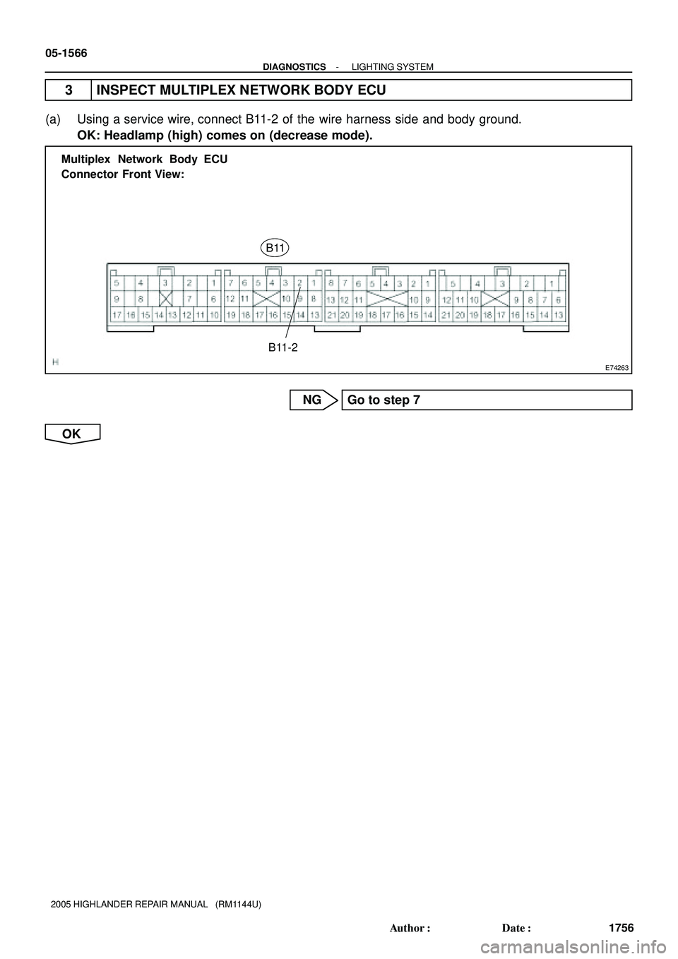
E74263
B11
B11-2 Multiplex Network Body ECU
Connector Front View:
05-1566
- DIAGNOSTICSLIGHTING SYSTEM
1756 Author�: Date�:
2005 HIGHLANDER REPAIR MANUAL (RM1144U)
3 INSPECT MULTIPLEX NETWORK BODY ECU
(a) Using a service wire, connect B11-2 of the wire harness side and body ground.
OK: Headlamp (high) comes on (decrease mode).
NG Go to step 7
OK
 Headlamp RH (Hi) DRL No.2 Relay
DRL No.3 Relay
DRL No.4
Relay When Daytime Running Light
System is Operated: 05-1562
- DIAGNOSTICSL")
 Headlamp RH (Hi) DRL No.2 Relay
DRL No.3 Relay
DRL No.4
Relay When HI Beam or Flash is
Operated:
- DIAGNOSTICSLIGHTING SYSTEM
05-1")

H3
Headlamp RH (High Beam)H2
Headlamp LH (Low Beam)
H1
Headlamp LH (High Beam)Engine Room R/B No.3
DRL No.4 Relay
Engine")