Page 1531 of 2572
E74076
Engine Room J/B
Body ECU
HEAD LAMP Relay
Engine Room R/B
H-LP RH LWR
H-LP LH LWR
H4
Headlamp RH (Low)H2
Headlamp LH (Low)
F7
FL Block
Battery FL MAINHRLY MAIN
L-R
R-B
W-B R-W
W-B R-Y
J3
J/C
EA3
B11 R 1
2B
1
2G 3
2 4
1 2 1 1
2I4
IK3
2
2
221
21
21
21
31W W
A
A 05-1556
- DIAGNOSTICSLIGHTING SYSTEM
1746 Author�: Date�:
2005 HIGHLANDER REPAIR MANUAL (RM1144U)
HEADLIGHT RELAY CIRCUIT
CIRCUIT DESCRIPTION
The multiplex network body ECU controls the HEAD relay when a signal is received from the headlamp dim-
mer switch assy.
WIRING DIAGRAM
05IQ9-01
Page 1532 of 2572

INSPECTION PROCEDURE
1 PERFORM AC")
E74263
B11
B11-3 Multiplex Network Body ECU
Connector Front View:
- DIAGNOSTICSLIGHTING SYSTEM
05-1557
1747 Author�: Date�:
2005 HIGHLANDER REPAIR MANUAL (RM1144U)
INSPECTION PROCEDURE
1 PERFORM ACTIVE TEST USING HAND-HELD TESTER
(a) Connect the hand-held tester to the DLC3.
(b) Turn the ignition switch to the ON position and turn the hand-held tester main switch on.
(c) Select the item below in the ACTIVE TEST and then check the relay operation.
BODY NO.1 (MULTIPLEX NETWORK BODY ECU):
ItemTest DetailsDiagnostic Note
HEAD LIGHTHeadlamp relay ON/OFF-
OK: Headlamp comes on.
NG Go to step 2
OK
PROCEED TO NEXT CIRCUIT INSPECTION SHOWN IN PROBLEM SYMPTOMS TABLE
(SEE PAGE 05-1538)
2 INSPECT MULTIPLEX NETWORK BODY ECU
(a) Disconnect the B11 connector from the multiplex network body ECU.
(b) Using a service wire, connect B11-3 of the wire harness side and body ground.
OK: Headlamp comes on.
NG Go to step 3
OK
PROCEED TO NEXT CIRCUIT INSPECTION SHOWN IN PROBLEM SYMPTOMS TABLE
(SEE PAGE 05-1538)
Page 1533 of 2572
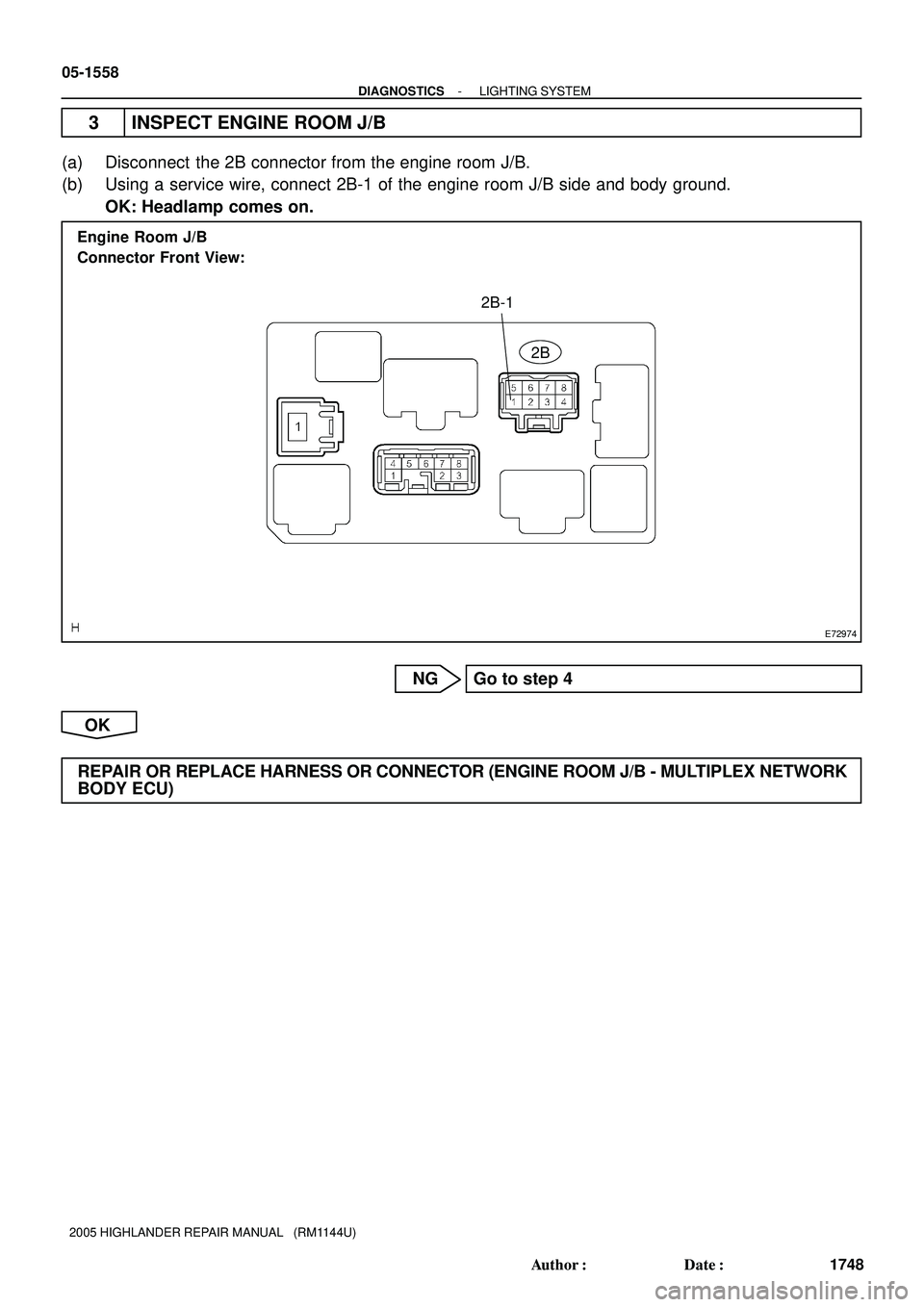
E72974
2B
2B-1 Engine Room J/B
Connector Front View:
05-1558
- DIAGNOSTICSLIGHTING SYSTEM
1748 Author�: Date�:
2005 HIGHLANDER REPAIR MANUAL (RM1144U)
3 INSPECT ENGINE ROOM J/B
(a) Disconnect the 2B connector from the engine room J/B.
(b) Using a service wire, connect 2B-1 of the engine room J/B side and body ground.
OK: Headlamp comes on.
NG Go to step 4
OK
REPAIR OR REPLACE HARNESS OR CONNECTOR (ENGINE ROOM J/B - MULTIPLEX NETWORK
BODY ECU)
Page 1534 of 2572
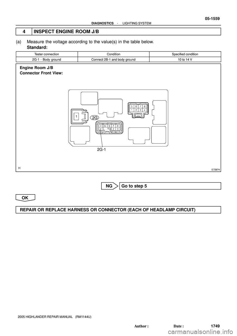
E72974
2G
2G-1 Engine Room J/B
Connector Front View:
- DIAGNOSTICSLIGHTING SYSTEM
05-1559
1749 Author�: Date�:
2005 HIGHLANDER REPAIR MANUAL (RM1144U)
4 INSPECT ENGINE ROOM J/B
(a) Measure the voltage according to the value(s) in the table below.
Standard:
Tester connectionConditionSpecified condition
2G-1 - Body groundConnect 2B-1 and body ground10 to 14 V
NG Go to step 5
OK
REPAIR OR REPLACE HARNESS OR CONNECTOR (EACH OF HEADLAMP CIRCUIT)
Page 1537 of 2572
E74079
Instrument Panel J/B
Body ECU
TAILLIGHT Relay
FOG LIGHT Relay
F2
Front Fog Lamp RH
F1
Front Fog Lamp LH
F7
FL BlockTRLY
FFGO TAIL
FR FOG
W-B
R-W R-W R-W
FL MAIN
BatteryALT4
12
53 1
1A BSB
V7
B9
6
B9
W
2
1
EG EA 12
122
1J
7
1B
W-B1J
A
A
J1
J/CJ3
J/C 12
35 05-1582
- DIAGNOSTICSLIGHTING SYSTEM
1772 Author�: Date�:
2005 HIGHLANDER REPAIR MANUAL (RM1144U)
FRONT FOG LIGHT CIRCUIT
CIRCUIT DESCRIPTION
The multiplex network body ECU controls the FOG relay when a signal is received from the headlamp dim-
mer switch assy.
WIRING DIAGRAM
05IQB-01
Page 1612 of 2572

OPERATION CHECK
1. ILLUMINATED ENTRY SYSTEM OPERATION CHECK
(a) Illuminated entry system co")
05ETG-02
05-1536
- DIAGNOSTICSLIGHTING SYSTEM
1726 Author�: Date�:
2005 HIGHLANDER REPAIR MANUAL (RM1144U)
OPERATION CHECK
1. ILLUMINATED ENTRY SYSTEM OPERATION CHECK
(a) Illuminated entry system controls the following lamps:
�Ignition key cylinder lamp
�Interior lamp (Room lamp assy No.1)
�Personal lamp (Overhead J/B)
(b) Check that the lamps come on after:
(1) Unlocking any door that was closed and locked with the ignition switch off.
(c) Check that the lamps fade out after:
(1) Leaving the doors unlocked for 15 seconds
(2) Turning the ignition switch to the ACC or ON position
(3) Locking all the doors
(d) Check that the lamps stay ON for at least 15 seconds after opening any of the doors, then fade out
again after 15 seconds.
(e) Check that the lamps fade out after:
(1) Leaving the doors unlocked for 15 seconds
(2) Locking all the doors
(f) Check that the lamps stay ON for at least 15 seconds after opening any of the doors, then fade out
again in 15 seconds after closing all the doors.
(g) Check that the lamps come on when opening any of the doors or turning the ignition switch off from
the ACC or ON position.
2. LIGHT AUTO TURN OFF OPERATION CHECK
(a) Turn the ignition switch to the ON position, and switch the headlamps into the TAIL or HEAD position.
(b) Turn the ignition switch off and open the driver's door, and check that the headlamps go off immediate-
ly.
(c) Turn the ignition switch to the ON position, and switch the headlamps into the AUTO position.
(d) Turn the ignition switch off and open the driver's door when operating the automatic light control sys-
tem, and check that the headlamps go off immediately.
3. AUTOMATIC LIGHT CONTROL OPERATION CHECK
HINT:
Perform the operation check at a location with bright surroundings.
(a) Turn the ignition switch to the ON position.
(b) Turn the headlamp dimmer switch to the AUTO position.
(c) Cover the automatic light control sensor and check that the taillamp and headlamp in order.
(d) Uncover the automatic light control sensor and check that the headlamp and taillamp go off in order.
4. DAYTIME RUNNING LIGHT OPERATION CHECK
(a) Check that the high beams come on when the headlamp switch is off with the engine running and park-
ing brake released.
(b) Check that the high beams go off when turning the headlamp dimmer switch into the TAIL or HEAD
(LOW) position under the condition as shown in (a).
(c) Check that the high beams go off when turning the ignition switch off under the condition as shown
in (a).
Page:
< prev 1-8 9-16 17-24
H2
Headlamp LH (Low)
F7
FL Block
Battery FL MAINHRLY MAIN
L-R
R-B
W-B R-W
W-B R-Y
J3
J/C
EA3")