Page 791 of 2572

F46309
Skid Control ECU with Actuator F7
FL Block
FL MAIN
Battery
EA EB ABS1+BS
GND1
J4
J/C 1831
32
AB W
W-BS27
S27 W-B
- DIAGNOSTICSABS WITH EBD & BA & TRAC & VSC SYSTEM
05-809
999 Author�: Date�:
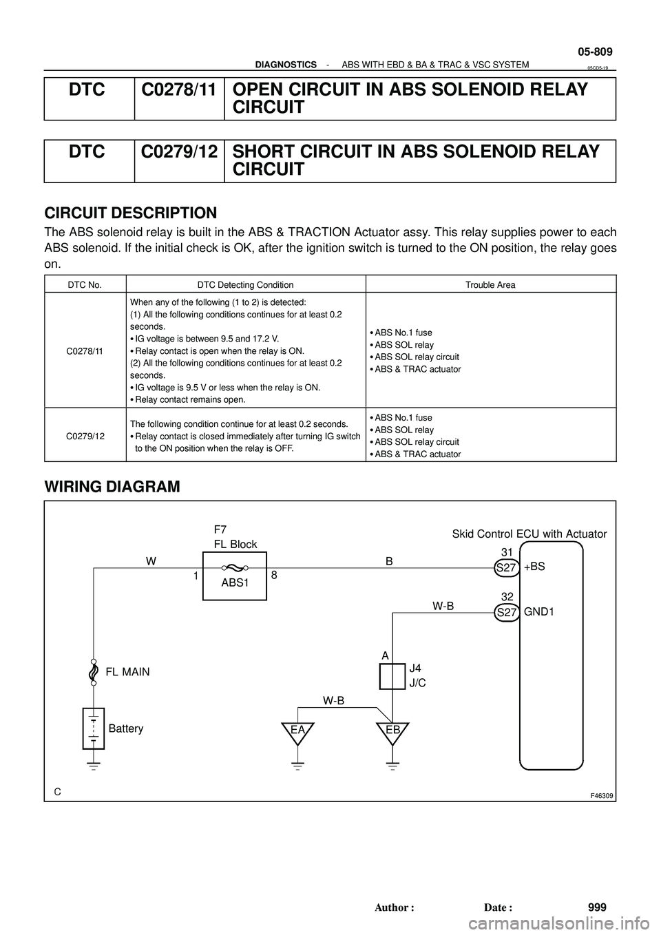
DTC C0278/11 OPEN CIRCUIT IN ABS SOLENOID RELAY
CIRCUIT
DTC C0279/12 SHORT CIRCUIT IN ABS SOLENOID RELAY
CIRCUIT
CIRCUIT DESCRIPTION
The ABS solenoid relay is built in the ABS & TRACTION Actuator assy. This relay supplies power to each
ABS solenoid. If the initial check is OK, after the ignition switch is turned to the ON position, the relay goes
on.
DTC No.DTC Detecting ConditionTrouble Area
C0278/11
When any of the following (1 to 2) is detected:
(1) All the following conditions continues for at least 0.2
seconds.
�IG voltage is between 9.5 and 17.2 V.
�Relay contact is open when the relay is ON.
(2) All the following conditions continues for at least 0.2
seconds.
�IG voltage is 9.5 V or less when the relay is ON.
�Relay contact remains open.
�ABS No.1 fuse
�ABS SOL relay
�ABS SOL relay circuit
�ABS & TRAC actuator
C0279/12
The following condition continue for at least 0.2 seconds.
�Relay contact is closed immediately after turning IG switch
to the ON position when the relay is OFF.�ABS No.1 fuse
�ABS SOL relay
�ABS SOL relay circuit
�ABS & TRAC actuator
WIRING DIAGRAM
05CD5-19
Page 1563 of 2572
A90349
Battery FL
MainInstrument Panel J/B Assy
L-Y
1 11C1Passenger Side J/B
P
F7
FL Block Assy Y
Combination Meter IC1
E511 I15
Ignition
Switch
WECM
GR
10
AM2
W1G6
4M4
4E1
W
IG2
AM26
7
IL19
IL2 10 J6
J/C
E
E P
SB
L
C11SB
C12 13 4
MIL IGN
- DIAGNOSTICSSFI SYSTEM (2AZ-FE)
05-359
549 Author�: Date�:
2005 HIGHLANDER REPAIR MANUAL (RM1144U)
MIL CIRCUIT
CIRCUIT DESCRIPTION
The Malfunction Indicator Lamp (MIL) is used to indicate the ECM's detection of a vehicle malfunction.
The instrument panel IG2 fuse provides circuit power and the ECM provides the circuit ground that illumi-
nates the MIL.
MIL operations should be checked visually:
The MIL should be illuminated when the ignition is first turned ON. If the MIL is always ON or OFF, use the
hand-held tester or OBD II
scan tool and follow the procedures to determine the cause of problem.
WIRING DIAGRAM
05EW1-05
Page 1816 of 2572
A90302
BATTECM
F7
FL Block Assy 32IEFI NO. 13
E5
11
BR
Battery1
E9
FL
MainE1 BR
A
A
BR
EE WEngine Room J/B
J7
J/C W
2B7
IK211
B-W
A90343EFI NO. 1 fuse Engine Room J/B
05-230
- DIAGNOSTICSSFI SYSTEM (2AZ-FE)
420 Author�: Date�:
2005 HIGHLANDER REPAIR MANUAL (RM1144U)
WIRING DIAGRAM
INSPECTION PROCEDURE
HINT:
Read freeze frame data using the hand-held tester or the OBD II scan tool. Freeze frame data records the
engine conditions when a malfunction is detected. When troubleshooting, freeze frame data can help deter-
mine if the vehicle was running or stopped, if the engine was warmed up or not, if the air-fuel ratio was lean
or rich, and other data from the time the malfunction occurred.
1 INSPECT FUSE (EFI NO. 1)
(a) Remove the EFI NO. 1 fuse from the engine room J/B.
(b) Measure the resistance of the EFI NO. 1 fuse.
Standard: Below 1 W
OK REPLACE FUSE
OK
Page 2056 of 2572
B80404
2A1G IC3
BATTERY FL MAIN W W
F7
FUSIBLE
LINK BLOCKEngine Room J/B
SECURITY ECU-B
D.C.C
3
12I
1 W - L5
BR
109 INSTRUMENT PANEL J/B ASSY
2A 451DP
EE J17
J/C
P11
IL1O2 Theft Warning ECU Assy T4
+B1
+B2
SH- 13
IF12
W 4
IC3L L
LG
IF3 17
B
2 IC3
T1
Theft Deterrent
Horn B - O
1
05-2028
- DIAGNOSTICSTHEFT DETERRENT SYSTEM
2218 Author�: Date�:
2005 HIGHLANDER REPAIR MANUAL (RM1144U)
THEFT DETERRENT HORN CIRCUIT
CIRCUIT DESCRIPTION
When the theft deterrent system is operating, the relay in the ECU turns on and off in a cycle of approximately
0.2 seconds, causing the theft warning horn to blow (see the wiring diagram below).
WIRING DIAGRAM
INSPECTION PROCEDURE
1 CHECK THEFT WARNING ECU ASSY (SECURITY)
(a) Remove the SECURITY fuse from the engine room J/B.
(b) Measure the resistance.
Standard: Below 1 W
NG REPAIR OR REPLACE HARNESS AND
CONNECTOR
OK
05ITM-04
Page 2166 of 2572

2005 HIGHLANDER (EWD592U)
9
B
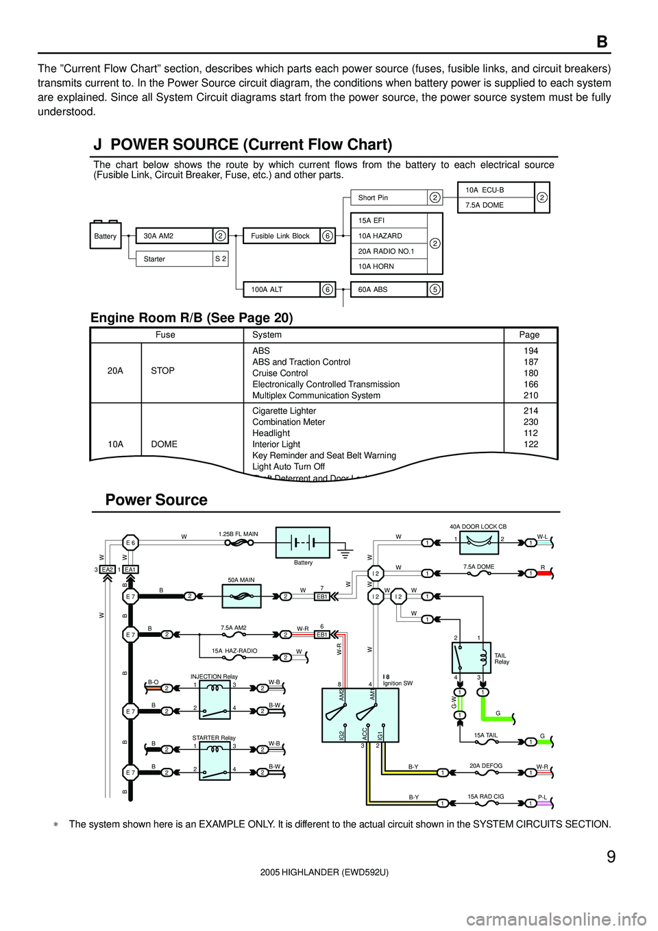
The ºCurrent Flow Chartº section, describes which parts each power source (fuses, fusible links, and circuit breakers)
transmits current to. In the Power Source circuit diagram, the conditions when battery power is supplied to each system
are explained. Since all System Circuit diagrams start from the power source, the power source system must be fully
understood.
ACC
S 26
652
22
Battery30A AM2
StarterShort Pin
100A ALT Fusible Link Block
60A ABS10A ECU-B
7.5A DOME
15A EFI
10A HAZARD
20A RADIO NO.1
10A HORN
20A
10AFusePage
214
230
11 2
122 194
187
180
166
210 ABS
Cigarette Lighter
Combination Meter
Key Reminder and Seat Belt Warning
Light Auto Turn Off
Theft Deterrent and Door Lock ControlABS and Traction Control
Cruise Control
Electronically Controlled Transmission
Multiplex Communication System STOPSystem
DOMEHeadlight
Interior Light
3 EA2 1 EA1E 6
E 7
E 7
2
2
2
2 2
2 2
2 INJECTION Relay
STARTER Relay B
B
B B-O
1
1 2
23
4
3
4W-B W-B
B-W
B-W E 7
E 7B
BW1.25B FL MAIN
50A MAIN
7.5A AM2
15A HAZ-RADIO 2
22
2
2W
WEB1
EB17
6
W-RI 2 I 2 I 2
WW
W W W
1 1
1 140A DOOR LOCK CB
7.5A DOME 1W-L
R 1
1
2
431
1 1
1
111 G
G
W-R 15A TAIL
20A DEFOG
B-Y 84
32Ignition SW I 8
B-Y
11P-L Battery
15A RAD CIG2
TAIL
Relay
Power Source J POWER SOURCE (Current Flow Chart)
Engine Room R/B (See Page 20)
2
W W
B B B B B
W-R
WW W
G-WAM2
AM1 IG2
IG1W
W
The chart below shows the route by which current flows from the battery to each electrical source
(Fusible Link, Circuit Breaker, Fuse, etc.) and other parts.
*The system shown here is an EXAMPLE ONLY. It is different to the actual circuit shown in the SYSTEM CIRCUITS SECTION.