Page 1353 of 2572
E74263
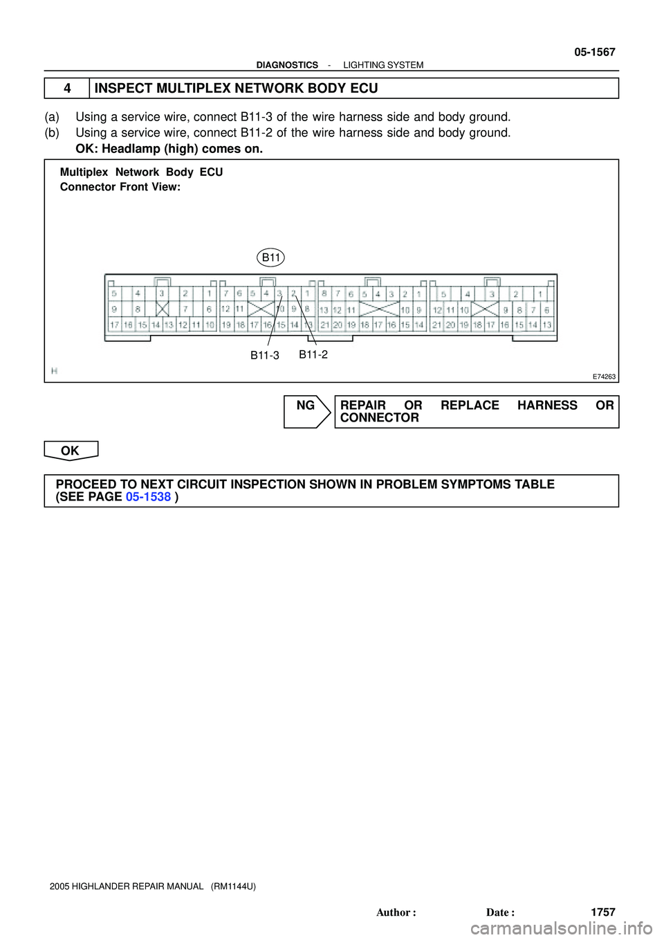
B11-2 Multiplex Network Body ECU
Connector Front View:
B11
B11-3
- DIAGNOSTICSLIGHTING SYSTEM
05-1567
1757 Author�: Date�:
2005 HIGHLANDER REPAIR MANUAL (RM1144U)
4 INSPECT MULTIPLEX NETWORK BODY ECU
(a) Using a service wire, connect B11-3 of the wire harness side and body ground.
(b) Using a service wire, connect B11-2 of the wire harness side and body ground.
OK: Headlamp (high) comes on.
NG REPAIR OR REPLACE HARNESS OR
CONNECTOR
OK
PROCEED TO NEXT CIRCUIT INSPECTION SHOWN IN PROBLEM SYMPTOMS TABLE
(SEE PAGE 05-1538)
Page 1356 of 2572
E72985
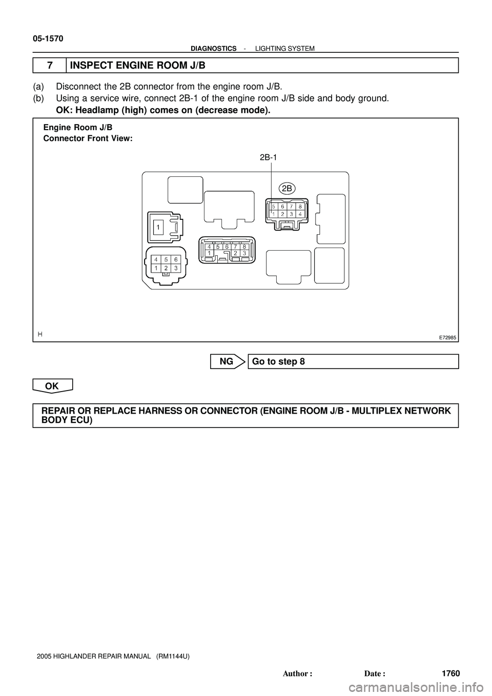
Engine Room J/B
Connector Front View:
2B
2B-1
05-1570
- DIAGNOSTICSLIGHTING SYSTEM
1760 Author�: Date�:
2005 HIGHLANDER REPAIR MANUAL (RM1144U)
7 INSPECT ENGINE ROOM J/B
(a) Disconnect the 2B connector from the engine room J/B.
(b) Using a service wire, connect 2B-1 of the engine room J/B side and body ground.
OK: Headlamp (high) comes on (decrease mode).
NG Go to step 8
OK
REPAIR OR REPLACE HARNESS OR CONNECTOR (ENGINE ROOM J/B - MULTIPLEX NETWORK
BODY ECU)
Page 1357 of 2572
E72985
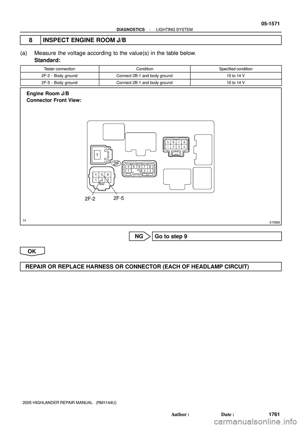
Engine Room J/B
Connector Front View:
2F
2F-5
2F-2
- DIAGNOSTICSLIGHTING SYSTEM
05-1571
1761 Author�: Date�:
2005 HIGHLANDER REPAIR MANUAL (RM1144U)
8 INSPECT ENGINE ROOM J/B
(a) Measure the voltage according to the value(s) in the table below.
Standard:
Tester connectionConditionSpecified condition
2F-2 - Body groundConnect 2B-1 and body ground10 to 14 V
2F-5 - Body groundConnect 2B-1 and body ground10 to 14 V
NG Go to step 9
OK
REPAIR OR REPLACE HARNESS OR CONNECTOR (EACH OF HEADLAMP CIRCUIT)
Page 1365 of 2572
05-1574
- DIAGNOSTICSLIGHTING SYSTEM
1764 Author�: Date�:
2005 HIGHLANDER REPAIR MANUAL (RM1144U)
TAIL RELAY CIRCUIT
CIRCUIT DESCRIPTION
The multiplex network body ECU controls the TAIL relay when a signal is received from the headlamp dim-
mer switch assy.
05IQA-01
Page 1373 of 2572

05IQ2-01
SettingLIGHT2 LIGHT1 NORMAL DARK2
DARK1
Lighting brightnessDark Bright
OLD
CURRENTBrightness of the sur-
rounding when lightingLighting delayDelay of turn-
ing light off**2
Old logic
New logic **1
('97/8-)6 sec.
15 sec.6 sec.
15 sec.3 sec.
15 sec.
**1: The new one has the logic to light up two times brighter than the old logic.
**2: Delay time until the headlamp is turned on when it suddenly gets dark.
- DIAGNOSTICSLIGHTING SYSTEM
05-1537
1727 Author�: Date�:
2005 HIGHLANDER REPAIR MANUAL (RM1144U)
CUSTOMIZE PARAMETERS
HINT:
The followings are the possible items to be customized.
NOTICE:
�After confirming whether the items of the customer's request are applicable or not for the cus-
tomized items, perform the customize operation.
�Be sure to record the current value before customizing.
�In case of performing the troubleshooting, pay attention as there is a possibility that the func-
tion is OFF by customizing. (Example: In case of the symptom in which ºThe wireless operation
does not functionº, check that the wireless operation is not OFF by customizing, then perform
the troubleshooting.)
ILLUMINATED ENTRY
DISPLAY(ITEM)DEFAULTCONTENTSSETTING
I/L ON / UNLOCK
(Interior lamp ON w/ door
key unlock)
ON
Function to light up the interior lamp*, ignition lamp and step
lamp when unlocking with the door key cylinder.
*: Interior lamp comes on when the interior lamp switch is at
the DOOR position.
ON / OFF
LIGHTING TIME
(Lighting Time)15 sTo change the lighting time after closing the door. (It will
quickly fade out in case of turning the ignition ON.)7.5 s / 15 s / 30 s
LIGHT CONTROL
HINT:
Sensitivity adjustment can hardly be confirmed. Please check by customer's actual driving.
DISPLAY(ITEM)DEFAULTCONTENTSSETTING
SENSITIVITY
(Turn ON luminous
intensity)
NORMALTo adjust the sensitivity of the lighting illumination.
Refer to the *1 illustration.DARK2 / DARK1 / NORMAL
/ LIGHT1 / LIGHT2
LIGHT CTRL TYPE
(Control Type)CURRENTTo change the control logic when the light control switch is in
the AUTO position. Refer to the *2 illustration.CURRENT / OLD
Illustration of *1
Illustration of *2
Page 1528 of 2572
E74080
Body ECU
Passenger Side J/B
C13
Combination Switch
Fog
Light SW
Light
Control SW
Dimmer SWFFOG
HU
HF
TAIL
HEAD
A
OFF
ON
OFF
TAIL
HEAD
AUTO
LOW
HIGH
FLASHBR
Y
O
V
LG
P 6
4F 2
4N Y
11
7
81413 12
1017
L16B10
W-B10
14
B10
15
B10
18
B10
17
B10
16
B10
IA
LFG BFG HU HL HF T H EL A
05-1586
- DIAGNOSTICSLIGHTING SYSTEM
1776 Author�: Date�:
2005 HIGHLANDER REPAIR MANUAL (RM1144U)
LIGHT CONTROL SWITCH CIRCUIT
CIRCUIT DESCRIPTION
This circuit detects the state of the headlamp dimmer switch.
WIRING DIAGRAM
05IQC-01
Page 1529 of 2572

E74263
Multiplex Network Body ECU
Connector Front View:
B10
B10-10
B10-14
B10-15
B10-16 B10-17 B10-18
- DIAGNOSTICSLIGHTING SYSTEM
05-1587
1777 Author�: Date�:
2005 HIGHLANDER REPAIR MANUAL (RM1144U)
INSPECTION PROCEDURE
1 INSPECT MULTIPLEX NETWORK BODY ECU
(a) Disconnect the B10 connector from the multiplex network body ECU.
(b) Measure the voltage according to the value(s) in the table below.
Standard:
Tester connectionConditionSpecified condition
B10-10 - Body groundFront fog light switch OFF " ON10 kW or higher " Below 1 W
B10-14 - Body groundHeadlamp Dimmer switch LOW " HIGH10 kW or higher " Below 1 W
B10-15 - Body groundHeadlamp Dimmer switch LOW " FLASH10 kW or higher " Below 1 W
B10-16 - Body groundLight control switch OFF " AUTO10 kW or higher " Below 1 W
B10-17 - Body groundLight control switch OFF " HEAD10 kW or higher " Below 1 W
B10-18 - Body groundLight control switch OFF " TAIL10 kW or higher " Below 1 W
NG Go to step 2
OK
PROCEED TO NEXT CIRCUIT INSPECTION SHOWN IN PROBLEM SYMPTOMS TABLE
(SEE PAGE 05-1538)
Page 1530 of 2572

2 INSPECT HEADLAMP DIMMER SWITCH ASSY
(a) Inspect light control swi")
E11948
Connector Front View:
C13
05-1588
- DIAGNOSTICSLIGHTING SYSTEM
1778 Author�: Date�:
2005 HIGHLANDER REPAIR MANUAL (RM1144U)
2 INSPECT HEADLAMP DIMMER SWITCH ASSY
(a) Inspect light control switch (when headlamp is malfunc-
tioning).
(1) Measure the resistance according to the value(s) in
the table below.
Standard:
Tester connectionConditionSpecified condition
12 - 16
13 - 16
14 - 16
OFF10 kW or higher
14 - 16TAILBelow 1 W
13 - 16
14 - 16HEADBelow 1 W
12 - 16AUTOBelow 1 W
(b) Inspect headlamp dimmer switch (when headlamp is mal-
functioning).
(1) Measure the resistance according to the value(s) in
the table below.
Standard:
Tester connectionConditionSpecified condition
16 - 17LOWBelow 1 W
7 - 16HIGHBelow 1 W
7 - 16
8 - 16FLASHBelow 1 W
(c) Inspect front fog light switch (when fog lamp is malfunc-
tioning).
(1) Measure the resistance according to the value(s) in
the table below.
Standard:
Tester connectionConditionSpecified condition
10 - 11OFF10 kW or higher
10 - 11ONBelow 1 W
NG REPLACE HEADLAMP DIMMER SWITCH ASSY
(SEE PAGE 65-25)
OK
REPAIR OR REPLACE HARNESS OR CONNECTOR