Page 497 of 2572
2005 HIGHLANDER (EWD592U)
182
VSC and Tire Pressure Warning System
A J16
A 21
11
W- B W- B
BR
12 IO213
W- L4C
B W
WL1D 9
GND CANH CANL ESSIG
CANH
L
O W- B
J19
L WW- B
8 19
BRSB SBV
BR SB SBV B WCANL
Y 1
S14
IG
1 10 9 25 1
20
BF 1G
W
104
P
2A7. 5A
ECU- B
P
BAT
3
J17
W
W- BG O
G
BGRY
4M
B
IO2 2
W
10E
YE
22 BR- W
B- R
BR- W
B- R GR
V
208IO2 3
3 11 4H
IC44C
IC4 102
2
9 44J
V 81 2 10 1D10A
ECU- IG
LG
LG
11K
V
IC3 5
BBA
W- B
W- B
W- BFrom Power Source System (
See Page 62)
Junction
Connector
Junction
Connector
Junction
Connector Steering Sensor
VSC War ning Buzzer
Yaw Rate SensorBuzzer
Page 621 of 2572
2005 HIGHLANDER (EWD592U)
262
Multiplex Communication System - CAN
7. 5A
ECU- B
2A 4
10 1G
BF 15
29101 IG1S14
Y 1CANL
W- B
W
L
J19
W- BOL
CANHIG
ESS CANL CANHGND 91D
W
B
4N 14C 3
IC
W- B
BR
A J16 10 1D10A
ECU- IG
W- L P
3BAT
Y W
E
21 10
19 8 22 11E
J17P
4J 44C2
4C 11IO2 3V
3 2
W
B
W- B G
W
IO2 12 IO213
B
W
920
Y
4L 7
W- B W- B
W- BV
IC3 5
BBA
W- B
W- B
IC4 12 IC4 13
25 11 14 6
W
B
CANL CANH CANHCANL
S27 D 3
A From Power Source System (
See Page 62)
Data Link Connector 3Junction
Connector
Junction
Connector
Junction
Connector Steering Sensor
Skid Control ECU
with Actuator
Yaw Rate Sensor
Page 797 of 2572

- DIAGNOSTICSABS WITH EBD & BA & TRAC & VSC SYSTEM
05-815
1005 Author�: Date�:
DTC C1210/36 ZERO POINT CALIBRATION OF YAW RATE
SENSOR UNDONE
DTC C1336/39 ZERO POINT CALIBRATION OF
DECELERATION SENSOR UNDONE
CIRCUIT DESCRIPTION
Brake actuator receives signals from the yaw rate sensor (deceleration sensor) via CAN communication sys-
tem.
Yaw rate sensor has the built-in G sensor.
If there is trouble in the bus lines between the yaw rate sensor (deceleration sensor) and CAN communica-
tion system, the DTC U0123/62 (yaw rate sensor communication trouble) and U0124/95 (G sensor commu-
nication trouble) are output.
DTC No.DTC Detecting ConditionTrouble Area
C1210/36Zero point calibration of yaw rate sensor undone
�Yaw rate sensor (Deceleration sensor)
�Zero point calibration undone
(Perform zero point calibration and DTC.
If DTC is not output again, the sensor is normal)
C1336/39
When all the following (1 to 2) is detected:
(1) Drives in normal mode before completing zero point
calibration.
(2) Zero point voltage is not within 2.38 V and 2.62 V at
zero point calibration.
�Yaw rate sensor (Deceleration sensor)
�Zero point calibration undone
(If DTC is not output again, the sensor is normal)
05F1R-07
Page 798 of 2572
05-816
- DIAGNOSTICSABS WITH EBD & BA & TRAC & VSC SYSTEM
1006 Author�: Date�:
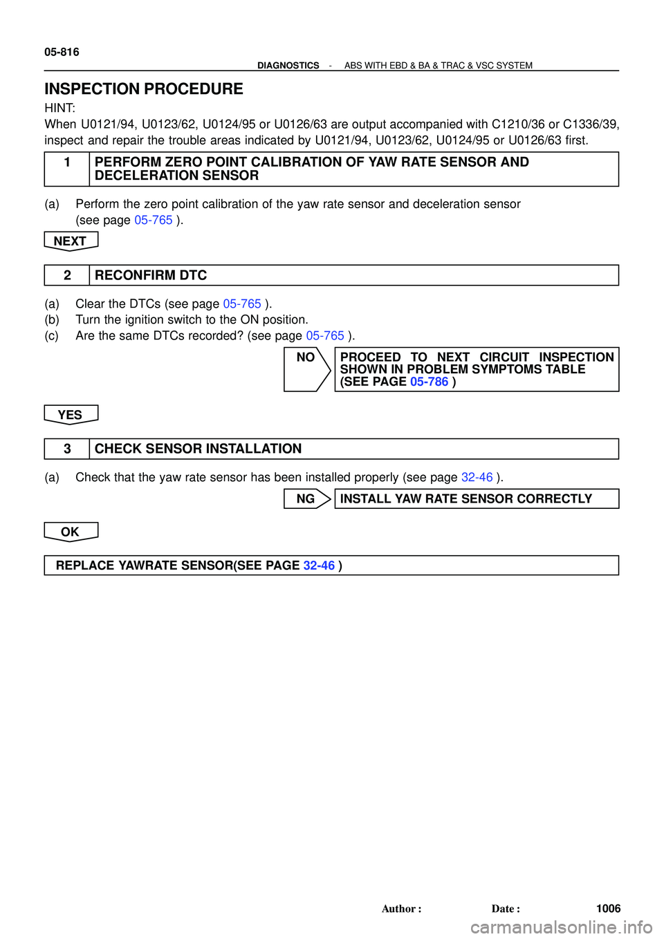
INSPECTION PROCEDURE
HINT:
When U0121/94, U0123/62, U0124/95 or U0126/63 are output accompanied with C1210/36 or C1336/39,
inspect and repair the trouble areas indicated by U0121/94, U0123/62, U0124/95 or U0126/63 first.
1 PERFORM ZERO POINT CALIBRATION OF YAW RATE SENSOR AND
DECELERATION SENSOR
(a) Perform the zero point calibration of the yaw rate sensor and deceleration sensor
(see page 05-765).
NEXT
2 RECONFIRM DTC
(a) Clear the DTCs (see page 05-765).
(b) Turn the ignition switch to the ON position.
(c) Are the same DTCs recorded? (see page 05-765).
NO PROCEED TO NEXT CIRCUIT INSPECTION
SHOWN IN PROBLEM SYMPTOMS TABLE
(SEE PAGE 05-786)
YES
3 CHECK SENSOR INSTALLATION
(a) Check that the yaw rate sensor has been installed properly (see page 32-46).
NG INSTALL YAW RATE SENSOR CORRECTLY
OK
REPLACE YAWRATE SENSOR(SEE PAGE 32-46)
Page 805 of 2572
 (-)(+)
(-)
S14
Steering Angle Sensor
(harness side connector)
- DIAGNOSTICSABS WITH EBD & BA & TRAC & VSC SYSTEM
05-823
1013 Author�: Date�:
INSPECTION PROCEDURE
HINT:
�When U012")
G26292
IG1
ESSBAT
(+) (-)(+)
(-)
S14
Steering Angle Sensor
(harness side connector)
- DIAGNOSTICSABS WITH EBD & BA & TRAC & VSC SYSTEM
05-823
1013 Author�: Date�:
INSPECTION PROCEDURE
HINT:
�When U0121/94, U0123/62, U0124/95 or U0126/63 are output together with C1231/31, inspect and
repair the trouble areas indicated by U0121/94, U0123/62, U0124/95 or U0126/63 first.
�When the speed sensor or the yaw rate sensor has trouble, DTCs for the steering angle sensor may
be output even when the steering angle sensor is normal. When DTCs for the speed sensor or yaw
rate sensor are output together with other DTCs for the steering angle sensor, inspect and repair the
speed sensor and yaw rate sensor first, and then inspect and repair the steering angle sensor.
�Start the inspection from step 1 when using the hand-held tester and start from step 2 when not using
the hand-held tester.
1 READ VALUE OF HAND-HELD TESTER(STEERING ANGLE SENSOR)
(a) Connect the hand-held tester to the DLC3.
(b) Start the engine.
(c) Select the DATA LIST mode on the hand-held tester.
(d) Check that the steering angle value of the steering angle sensor indicated on the hand-held tester,
changes when the steering wheel is turned.
ItemMeasurement Item /
Range (Display)Normal Condition
STEERING ANGSteering sensor/
Min.: -1152 deg, Max.: 1150.875 degMin.: -128 deg/s
Max.: 128 deg/s
OK:
Steering angle value should change.
OK REPLACE ABS & TRACTION ACTUATOR ASSY
(SEE PAGE 32-37)
NG
2 CHECK TERMINAL VOLTAGE(STEERING ANGLE SENSOR CONNECTOR)
(a) Remove the steering wheel and the column lower cover.
(b) Disconnect the steering angle sensor connector S14.
(c) Turn the ignition switch to the ON position.
(d) Measure the voltage according to the value(s) in the table
below.
Standard:
Tester ConnectionSpecified Condition
S14-1 (IG1) - S14-2 (ESS)10 to 14 V
S14-3 (BAT) - S14-2 (ESS)10 to 14 V
NG REPAIR OR REPLACE HARNESS OR
CONNECTOR
OK
REPLACE STEERING ANGLE SENSOR
Page 806 of 2572

05-824
- DIAGNOSTICSABS WITH EBD & BA & TRAC & VSC SYSTEM
1014 Author�: Date�:
DTC C1232/32 MALFUNCTION IN DECELERATION SENSOR
DTC C1234/34 MALFUNCTION IN YAW RATE SENSOR
DTC C1243/43 MALFUNCTION IN DECELERATION SENSOR
DTC C1244/44 OPEN OR SHORT IN DECELERATION
SENSOR CIRCUIT
DTC C1245/45 MALFUNCTION IN DECELERATION SENSOR
DTC C1381/97 MALFUNCTION IN POWER SUPPLY
VOLTAGE YAW/DECELERATION SENSOR
CIRCUIT DESCRIPTION
The yaw rate sensor and deceleration sensor signals are sent to the skid control ECU through the CAN com-
munication system. When there is a malfunction in the communication, it will be detected by the diagnosis
function.
DTC No.DTC Detecting ConditionTrouble Area
C1232/32
While the vehicle is at a speed of 6mph (10 km/h) or more,
the condition that the fluctuation range of the signal from
either GL1 or GL2 is under 80 mV and the other is above
1.9 V continues for 30 seconds or more.
�Yaw rate/deceleration sensor
�Yaw rate/deceleration sensor circuit
C1234/34Slftiiliif t�Yaw rate/deceleration sensorC1234/34Sensor malfunction signal is reccives from yaw rate sensor.�Ya w rate/deceleration sensor
�Yaw rate/deceleration sensor circuit
C1243/43
The following condition repeats 16 times.
�GL1 and GL2 do not change by more than 2LSB when the
vehicle decelerates from 19 mph (30 km/h) to 0 mph (0
km/h).
�Yaw rate/deceleration sensor
�Yaw rate/deceleration sensor circuit
C1244/44
When any of the following (1 to 2) is detected:
(1) All the following conditions continues for at least 60 se-
conds.
�Vehicle is stopped.
�Difference between IGL1I and IGL2I does not drop below
0.4 G once it reaches 0.6 G or more.
(2) Data malfunction signal is received from G sensor.
�Yaw rate/deceleration sensor
�Yaw rate/deceleration sensor circuit
C1245/45
The following condition continue for at least 60 seconds.
�Difference between the values calculated from G sensor
value and vehicle speed exceeds 0.35 G.�Yaw rate/deceleration sensor
�Yaw rate/deceleration sensor circuit
C1381/97�G sensor power source malfunction signal is received for
at least 10 sec. at a speed of more than 2 mph (3 km/h).�Yaw rate/deceleration sensor
�Yaw rate/deceleration sensor circuit
05CDB-18
Page 807 of 2572
F46306
Skid Control ECU
with Actuator Y1
Yaw Rate Sensor
Passenger Side J/B
Instrument Panel J/B I15
Ignition SW
F7
FL Block
FL MAIN
Battery GND
IG
ALTJ19
J/C
BF CANL
CANHCANL
CANH
AM1 IG1ECU-IG
AM1 IO2IC4
1A 1C 1D 4C 4J
1CS27
S27
IO2 IO2 IC4J16
J/C
12
3
4
5
6 7 9
1011 19 2025
12 13
3812 13
2
24
121
1 2B GL
OVW
Y WWW
G
WB B
W
A
A W-B
W-B
- DIAGNOSTICSABS WITH EBD & BA & TRAC & VSC SYSTEM
05-825
1015 Author�: Date�:
WIRING DIAGRAM
INSPECTION PROCEDURE
HINT:
When U0121/94, U0123/62, U0124/95 or U0126/63 are output together with C1232/32 or C1334/34, inspect
and repair the trouble areas indicated by U0121/94, U0123/62, U0124/95 or U0126/63 first.
1 CHECK SENSOR INSTALLATION(YAW RATE SENSOR)
(a) Check that the yaw rate and deceleration sensor has been installed properly (see page 32-46).
NG INSTALL YAW RATE SENSOR CORRECTLY
(SEE PAGE 32-46)
OK
Page 808 of 2572
F45082IG Yaw Rate Sensor
(harness side connector)
Y1
F45082
GND
Yaw Rate Sensor
(harness side connector)
Y1
05-826
- DIAGNOSTICSABS WITH EBD & BA & TRAC & VSC SYSTEM
1016 Author�: Date�:
2 CHECK HARNESS AND CONNECTOR(IG TERMINAL)
(a) Disconnect the yaw rate sensor connector.
(b) Turn the ignition switch to the ON position.
(c) Measure the voltage according to the value(s) in the table
below.
Standard:
Tester ConnectionSpecified Condition
Y1-5 (IG) - Body ground10 to 14 V
NG REPAIR OR REPLACE HARNESS OR
CONNECTOR
OK
3 CHECK HARNESS AND CONNECTOR(GND TERMINAL)
(a) Disconnect the yaw rate sensor connector.
(b) Measure the resistance according to the value(s) in the
table below.
Standard:
Tester ConnectionSpecified Condition
Y1-1 (GND) - Body groundBelow 1 W
NG REPAIR OR REPLACE HARNESS OR
CONNECTOR
OK
REPLACE ABS & TRACTION ACTUATOR ASSY (SEE PAGE 32-37)

182
VSC and Tire Pressure Warning System
A J16
A 21
11
W- B W- B
BR
12 IO213
W- L4C
B W
WL1D 9
GND CANH CANL ESSIG
CANH
L
O W- B
J19
L WW- B
8 19
BRSB SBV
BR SB SBV B WCANL
Y")

262
Multiplex Communication System - CAN
7. 5A
ECU- B
2A 4
10 1G
BF 15
29101 IG1S14
Y 1CANL
W- B
W
L
J19
W- BOL
CANHIG
ESS CANL CANHGND 91D
W
B
4N 14C 3
IC
W- B
BR
A J16 10 1")