Page 2155 of 2572
2005 HIGHLANDER (EWD592U)
318
I GROUND POINT
Door Lock Motor
Rear RH
Power Window SW
Rear RH BC113
BC112
W- BW- B
BBW- B
W- B
Seat Heater SW RH BM11
W- BW- B
Stereo Power
Amplifier Wireless Door
Lock ECU Yaw Rate Sensor Char coal Canister
Assembly Rear Heater Blower
Motor Rear Heater Relay Rear Heater
Blower SWA
A
A
A
A
A
A
A BJ115 W- B
W- B
W- B
W- B
W- B W- B
W- B
W- B
W- B
BF
W- B
ARear Seat
Entertainment
ECU
(
SELD) (
GND)
J19
Occupant
Classification
ECU BL13
W- B W- B
W- B
W- B C
C
C
W- B
J18
C A
W- B
B A B A
A A Power Seat
Control SW
(
Front Passenger' s
Seat Contr ol)W- B
W- B W- B
(
*4)
(
*5) (
*5) (
*4) (
*4)* 4 : w/ Power Seat(
Front Passenger' s Seat)
* 5 : w/o Power Seat(
Front Passenger' s Seat)
(
E)(
GND) Door Unlock
Detection SW
Rear RH J23(
A)
, J24(
B)
Junction
Connector Junction
Connector
Junction Connector
Page 2289 of 2572
2005 HIGHLANDER (EWD592U)
M OVERALL ELECTRICAL WIRING DIAGRAM
1112
10 9
15 HIGHLANDER (
Cont' d)
L
W G
W
B
W
Y
W Data Link Connect or 3
<2- 18><3- 14>
L P
W- B P
13
2910CA NL CA NH IG1 BAT
ESS
SB B
CP
P
GVA 11 B 6 B 11 A 17 L V
B W
O VW-B32 5
1 GNDCA NH CA NL IG
BFNear the Rear
Side Mark er Light RH
W- B
13
7B
SB
BR
W
L
P WB GR SB
IBRBR
Speedometer
VSC Brake
A
3K 23B 12
Right Instrument
Panel Brace A
H
I
VSC and Tire Pressure W arning System
D
F
J
K
M u ltip le x C o m m u n ic a tio n S y s te m (
CAN)
3IO2 12IO2 13IO2
G W
E E
21 10 22 11 20 9
19 8 9IL1 P
ABSBR
16 IF3 6 IF2 6 IF3 18 IF3
BR
SB
SB
15 IF3
EB Right Front
Fender Apr on
VR R-BA B
E7
3C 4
3A
1A
P
B 10
1IC4
A A
BBRight Center
Pillar
W- B
J19
A
W- B
Slip
TRAC OFF
Tire Air
Pressure (
2WD)(
2WD)
LW- B
W- B
C1 1(
A)
, C12(
B)
B 4
J16 Y 1
J19J17
J 4Brake Warning SW
Combination Meter
Junc tion
Connec torJunction Connector
Junct ion
Connect or
Junction
Connector
Steering Sens or
Yaw Rate Sensor
S14
2 1
Page 2330 of 2572
05CD0-06
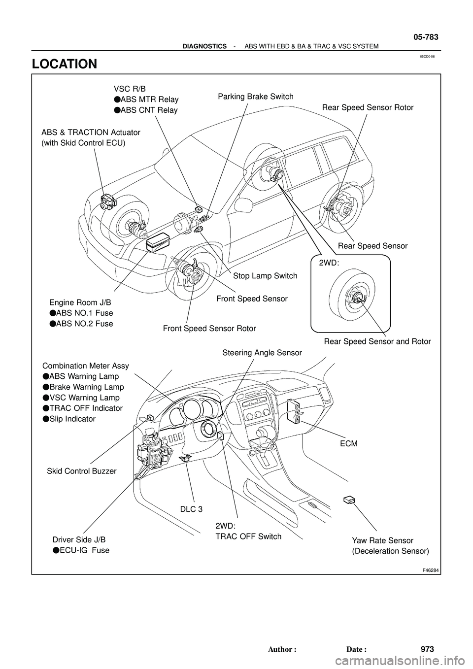
F46284
Rear Speed Sensor and Rotor
ABS & TRACTION Actuator
(with Skid Control ECU)
Engine Room J/B
�ABS NO.1 Fuse
�ABS NO.2 Fuse
Combination Meter Assy
�ABS Warning Lamp
�Brake Warning Lamp
�VSC Warning Lamp
�TRAC OFF Indicator
�Slip Indicator
Driver Side J/B
�ECU-IG FuseStop Lamp Switch
2WD:
TRAC OFF Switch DLC 3
VSC R/B
�ABS MTR Relay
�ABS CNT Relay
Yaw Rate Sensor
(Deceleration Sensor)
ECM
Steering Angle Sensor
Skid Control Buzzer
Front Speed Sensor
Front Speed Sensor Rotor
2WD:
Parking Brake Switch
Rear Speed Sensor Rear Speed Sensor Rotor
- DIAGNOSTICSABS WITH EBD & BA & TRAC & VSC SYSTEM
05-783
973 Author�: Date�:
LOCATION
Page 2335 of 2572

345
S28Short Connector90980-12366
S29Short Connector90980-12365
S30Short Connector90980-10859
S31Short Connector90980-108")
L
CodePart Name Part NumberCodePart Name Part Number
2005 HIGHLANDER (EWD592U)
345
S28Short Connector90980-12366
S29Short Connector90980-12365
S30Short Connector90980-10859
S31Short Connector90980-10860
S32Side Airbag Sensor Rear LH90980-12225S33Side Airbag Sensor Rear RH90980-12225
T 1Theft Deterrent Horn90980-10619
T 3Turbine Speed Sensor90980-1 1156
T 4Theft Deterrent ECU90980-12169
T 5Theft Deterrent Indicator Light90980-12063
T 6TRAC Off SW90980-1 1013
T 7Transponder Key Amplifier90980-12092
T 8Turn Signal Flasher90980-10799
T 9Towing Converter90980-1 1527
T10Trailer Hitch90980-10794
T11Tweeter LH90980-1 1013T12Tweeter RH90980-1 1013
T13Throttle Control Motor90980-1 1858T13Throttle Position Sensor90980-11858
T14Transponder Key Computer90980-1 1911
T15Telltale Light Assembly
Indicator Light Wire Sub Assembly90980-12221T16Transmission Control SW90980-12221
Transmission Shift Main SW
V 2VSV (ACIS No.2)90980-1 1149
V 4VSV (EVAP)90980-1 1156V 5VSV (ACM)90980-11156
V 6VVT Sensor LH90980-10947V 7VVT Sensor RH90980-10947
V 8VSC Warning Buzzer90980-10906
V9Garage Door OpenerV 9Vanity Light LH90980-1 1369
V10Vanity Light RH
V11Vapor Pressure Sensor90980-1 1860
V13Video Terminal90980-12221
V14VSV (Canister Closed Valve)90980-1 1859
V15Voltage Inverter90980-10799
W 1Washer Level Sensor90980-1 1068
W 3Water Temp. SW No.190980-1 1235
W 4Water Temp. SW No.290980-1 1243
W 5Wireless Door Lock Buzzer90980-1 1142
W 6Wireless Door Lock ECU90980-1 1909
Y 1Yaw Rate Sensor90980-1 1904
Page 2343 of 2572

45
G
Position of Parts in Body
R 7 Rear Combination Light LH
R 8 Rear Combination Light RH
R 9 Rear Door Speaker LH
R 10 Rear Door Speaker RH
R 11 Rear Interior Light
R 12")
2005 HIGHLANDER (EWD592U)
45
G
Position of Parts in Body
R 7 Rear Combination Light LH
R 8 Rear Combination Light RH
R 9 Rear Door Speaker LH
R 10 Rear Door Speaker RH
R 11 Rear Interior Light
R 12 Rear Interior Light SW
R 13 Rear Power Outlet
R 14 Rear Side Marker Light LH
R 15 Rear Side Marker Light RH
R 16 Rear Window Defogger
R 17 Rear Window Defogger
R 18 Rear Wiper Motor
R 19 Remote Control Mirror LH
R 20 Remote Control Mirror RH
R 25 Rear Heater Blower Motor
R 26 Rear Heater Blower SW
R 27 Rear Heater Relay
R 28 Rear Seat Entertainment Display
R 29 Rear Seat Entertainment ECU
R 30 Rear Seat Entertainment ECU
R 31 Rear Seat Entertainment ECUS 16 Side Airbag Sensor Front LH
S 17 Side Airbag Sensor Front RH
S 20 Sliding Roof Control ECU
S 22 Stereo Power Amplifier
S 23 Stereo Power Amplifier
S 32 Side Airbag Sensor Rear LH
S 33 Side Airbag Sensor Rear RH
T 9 Towing Converter
T 10 Trailer Hitch
T 11 Tweeter LH
T 12 Tweeter RH
V 9 Garage Door Opener
Vanity Light LH
V 10 Vanity Light RH
V 11 Vapor Pressure Sensor
V 13 Video Terminal
V 14 VSV (Canister Closed Valve)
V 15 Voltage Inverter
W 6 Wireless Door Lock ECU
Y 1 Yaw Rate Sensor
Page 2362 of 2572

SFLHABS solenoid (SFLH) / ON
or OFFON : Operate-
S")
- DIAGNOSTICSABS WITH EBD & BA & TRAC & VSC SYSTEM
05-769
959 Author�: Date�: ItemDiagnostic Note Normal Condition Measurement Item /
Range (Display)
SFLHABS solenoid (SFLH) / ON
or OFFON : Operate-
SRRR (SRR)ABS solenoid (SRRR
(SRR)) / ON or OFFON : Operate-
SRRH (SRH)ABS solenoid (SRRH
(SRH)) / ON or OFFON : Operate-
SRLRABS solenoid (SRLR) / ON
or OFFON : Operate-
SRLHABS solenoid (SRLH) / ON
or OFFON : Operate-
SMF (BA-SOL)TRAC solenoid (SMF) /
ON or OFFON : Operate-
SMRTRAC solenoid (SMR) /
ON or OFFON : Operate-
THROTTLEThrottle position sensor/
Min.: 0 deg, Max.: 125 deg
Release accelerator pedal:
Approx. 0 deg.
Depress accelerator pedal:
Approx. 90 deg.
-
ENGINE SPD
Engine Speed/
Min.: 0 rpm, Max.: 6,000
rpm
Actual engine speed-
VEHICLE SPD
Maximum wheel speed
sensor reading / min.: 0
km/h (0 MPH), max.: 326
km/h (202 MPH)
Actual vehicle speedSimilar speed as indicated
on speedometer
YAW RATE
Yaw rate sensor/
Min.: -128 deg/s, Max.:
128 deg/sMin.: -128 deg/s
Max.: 128 deg/s-
YAW ZERO VALUE
Memorized zero value/
Min.: -128 deg/s, Max.:
128 deg/sMin.: -128 deg/s
Max.: 128 deg/s-
STEERING ANG
Steering sensor/
Min.: -1152 deg,
Max.: 1150.875 degLeft turn: Increase
Right turn: Decrease-
MAS CYL PRS 1
Master cylinder pressure
sensor 1 reading / min.: 0
V, max.: 5 VWhen brake pedal is re-
leased : 0.3 to 0.9 VReading increases when
brake pedal is depressed
TEST MODETest mode / NORMAL or
TESTNORMAL : Normal mode
TEST : During test mode-
#CODESNumber of DTC recorded /
min.: 0, max.: 255Min.: 0, max.: 39-
Page 2364 of 2572

- DIAGNOSTICSABS WITH EBD & BA & TRAC & VSC SYSTEM
05-771
961 Author�: Date�: ItemDiagnostic Note Vehicle Condition / Test Details
BRAKE WRN LIGHTTurns BRAKE warning light ON / OFFObserve combination me-
ter
VSC / BR WARN BUZTurns VSC / BRAKE warning buzzer ON / OFFBuzzer can be heard
*: 2WD only
6. FREEZE FRAME DATA
HINT:
�Whenever a DTC is detected or the ABS operates, the skid control ECU stores the current vehicle (sen-
sor) state as freeze frame data.
�The skid control ECU stores the number of times (maximum: 31) the ignition switch has been turned
from off to the On position since the last time ABS was activated. However, if the vehicle was stopped
or at low speed (4.3 mph (7 km/h) or less), or if a DTC is detected, the skid control ECU will not count
the number since then.
�Freeze frame data at the time the ABS operates:
The skid control ECU stores and updates data whenever the ABS system operates.
When the ECU stores data at the time a DTC is detected, the data stored when the ABS operated is
erased.
�Freeze frame data at the time a DTC is detected:
When the skid control ECU stores data at the time a DTC is detected, no updates will be performed
until the data is cleared.
(a) Connect the Hand-held tester to the DLC3.
(b) Turn the ignition switch to the ON position.
(c) From the display on the tester, select the ºFREEZE FRAME DATAº.
Hand-held tester displayMeasurement ItemReference Value
VEHICLE SPDWheel speed sensor readingSpeed indicated on speedometer
STOP LIGHT SWStop lamp switch signalStop lamp switch ON: ON, OFF: OFF
# IG ONNumber of operations of ignition switch ON after
memorizing freeze frame data0 to 31
MAS CYL PRESSMaster cylinder pressure sensor readingBrake pedal release : 0.3 to 0.9 V
Brake pedal depress: 0.8 to 4.5 V
MASS PRESS GRADEMaster cylinder pressure sensor change-30 to 200 MPa/s
SYSTEMSystem status
ABS activated: ABS
VSC/TRC activated: VSC/TRC
BA activated: BA
Fail safe mode activated: FAIL SF
No system activated: NO SYS
YAW R AT EYaw rate angle sensor reading-100 to 100
STEERING ANGSteering sensor readingLeft turn: Increase
Right turn: Decrease
G (RIGHT & LEFT)Right and left G-1.869 to 1.869
G (BACK & FORTH)Back and forth G-1.869 to 1.869
VSC (TRC) OFF SW*TRAC control switch signalTRC control switch ON: ON
OFF: OFF
SHIFT POSITIONShift lever position
FAIL
P, N
R
D
4
3
2
L
THROTTLEThrottle sensor reading0 to 125 deg.
*: 2WD only
Page 2365 of 2572

(USING SST CHECK WIRE)
NOTICE:
Afte")
C52361
DLC3
Ts
CG
BR3904
0.13 sec. 0.13 sec.
ON
OFF 05-772
- DIAGNOSTICSABS WITH EBD & BA & TRAC & VSC SYSTEM
962 Author�: Date�:
7. SENSOR SIGNAL CHECK (TEST MODE)
(USING SST CHECK WIRE)
NOTICE:
After replacing the yaw rate sensor (deceleration sensor)
and/or brake actuator assembly (skid control ECU), per-
form zero point calibration of the yaw rate sensor and de-
celeration sensor. (See step 9.)
HINT:
�If the ignition switch is turned from ON to the ACC or
LOCK position during test mode, DTC of sensor check
function will be erased.
�During test mode, ECU records all DTCs of sensor check
functions. By preforming sensor signal check, the codes
are erased if normality is confirmed. The codes left over
are the codes where an abnormality was found.
(a) Procedures for test mode:
(1) Turn the ignition switch off.
(2) Check that the steering wheel is in the straight-
ahead position and shift the shift lever to the P posi-
tion.
(3) Using SST, connect terminals Ts and CG of the
DLC3.
SST 09843-18040
(4) Turn the ignition switch to the ON position.
(5) Check that the ABS warning light and VSC warning
light blink.
HINT:
If the ABS warning light and VSC warning light do not blink, in-
spect the ABS warning light circuit, VSC warning light and Ts
terminal circuit.
Trouble areaSee Page
Ts and CG terminal circuit05-873
ABS warning light circuit05-840 or
05-844
VSC warning light circuit05-847 or
05-851
(b) Check the master cylinder pressure sensor:
(1) Leave the vehicle in a stationary condition and the
brake pedal in a free condition for 1 second or more,
and quickly depress the brake pedal with a force of
98 N (10 kgf, 22 lbf) or more for 1 second or more.
HINT:
�At this time, the ABS warning light remains on for 3 se-
conds.
�While the ABS warning light remains on, continue to de-
press the brake pedal with a force of 98 N (10 kgf) or more.
�The ABS warning light comes on for 3 seconds every time
the brake pedal operation above is performed.

318
I GROUND POINT
Door Lock Motor
Rear RH
Power Window SW
Rear RH BC113
BC112
W- BW- B
BBW- B
W- B
Seat Heater SW RH BM11
W- BW- B
Stereo Power
Amplifier Wireless Door
Lock")

M OVERALL ELECTRICAL WIRING DIAGRAM
1112
10 9
15 HIGHLANDER (
Cont d)
L
W G
W
B
W
Y
W Data Link Connect or 3
<2- 18><3- 14>
L P
W- B P
13
2910CA NL CA NH IG1 BAT
ESS
SB")