Page 1444 of 2572

05-346
- DIAGNOSTICSSFI SYSTEM (2AZ-FE)
536 Author�: Date�:
2005 HIGHLANDER REPAIR MANUAL (RM1144U)
Monitor Confirmation
HINT:
After a repair, check Monitor Status by performing the Key-Off Monitor Confirmation and Purge Flow Monitor
Confirmation described below.
1. KEY-OFF MONITOR CONFIRMATION
(a) Preconditions
The monitor will not run unless:
�The vehicle has been driven for 10 minutes or more (in a city area or on a free way)
�The fuel tank is less than 90% full
�The altitude is less than 8,000 ft (2,400 m)
�The Engine Coolant Temperature (ECT) is between 4.4�C and 35�C (40�F and 95�F)
�The Intake Air Temperature (IAT) is between 4.4�C and 35�C (40�F and 95�F)
�The vehicle remains stationary (the vehicle speed is 0 mph [0 km/h])
(b) Monitor Conditions
(1) Allow the engine to idle for at least 5 minutes.
(2) Turn the ignition switch OFF and wait for 6 hours (8 or 10.5 hours).
HINT:
Do not start the engine until checking MONITOR STATUS. If the engine is started, the steps described above
must be repeated.
(c) Monitor Status
(1) Connect a hand-held tester to the DLC3.
(2) Turn the ignition switch ON and turn the tester ON.
(3) On the tester, select the following menu items: DIAGNOSIS / ENHANCED OBD II / MONITOR
STATUS.
(4) Check the Monitor Status displayed on the tester.
HINT:
If INCMP is displayed, the monitor is not completed. Make sure that the preconditions have been met, and
perform the Monitor Conditions again.
2. PURGE FLOW MONITOR CONFIRMATION (P0441)
HINT:
Perform this monitor confirmation after the Key-Off Monitor Confirmation shows COMPL (complete).
(a) Preconditions
The monitor will not run unless:
�The vehicle has been driven for 10 minutes or more (in a city area or on a free way)
�The ECT is between 4.4�C and 35�C (40�F and 95�F)
�The IAT is between 4.4�C and 35�C (40�F and 95�F)
(b) Monitor Conditions
(1) Release the pressure from the fuel tank by removing and reinstalling the fuel tank cap.
(2) Warm the engine up until the ECT reaches more than 75�C (167�F).
(3) Increase the engine speed to 3,000 rpm once.
(4) Allow the engine to idle and turn A/C ON for 1 minute.
(c) Monitor Status
(1) Turn the ignition switch OFF (where ON or the engine is running).
(2) Connect a hand-held tester to the DLC3.
(3) Turn the ignition switch to ON and turn the tester ON.
(4) On the tester, select the following menu items: DIAGNOSIS / ENHANCED OBD II / MONITOR
STATUS.
(5) Check the Monitor Status displayed on the tester.
Page 1758 of 2572

A85838
Waveform of A/F Sensor
Before CatalystWaveform of Heated Oxygen Sensor
After Catalyst Normal Catalyst
Deteriorated Catalyst Waveform of A/F Sensor
Before CatalystWaveform of Heated Oxygen Sensor
After Catalyst 3.5 V
3.0 V
3.5 V
3.0 V1.0 V
0.5 V
1.0 V
0.5 V
10 seconds 10 seconds
0 V 0 V 05-184
- DIAGNOSTICSSFI SYSTEM (2AZ-FE)
374 Author�: Date�:
2005 HIGHLANDER REPAIR MANUAL (RM1144U)
DTC P0420 CATALYST SYSTEM EFFICIENCY BELOW
THRESHOLD (BANK 1)
MONITOR DESCRIPTION
The ECM uses sensors mounted before and after the three-way catalyst (TWC) to monitor its efficiency. The
first sensor, an Air Fuel ratio (A/F) sensor, sends pre-catalyst A/F ratio information to the ECM. The second
sensor, a heated oxygen sensor (O2S), sends post-catalyst information to the ECM. The ECM compares
these two signals to judge the efficiency of the catalyst and the catalyst's ability to store oxygen. During nor-
mal operation, the TWC stores and releases oxygen as needed. The capacity to store oxygen results in a
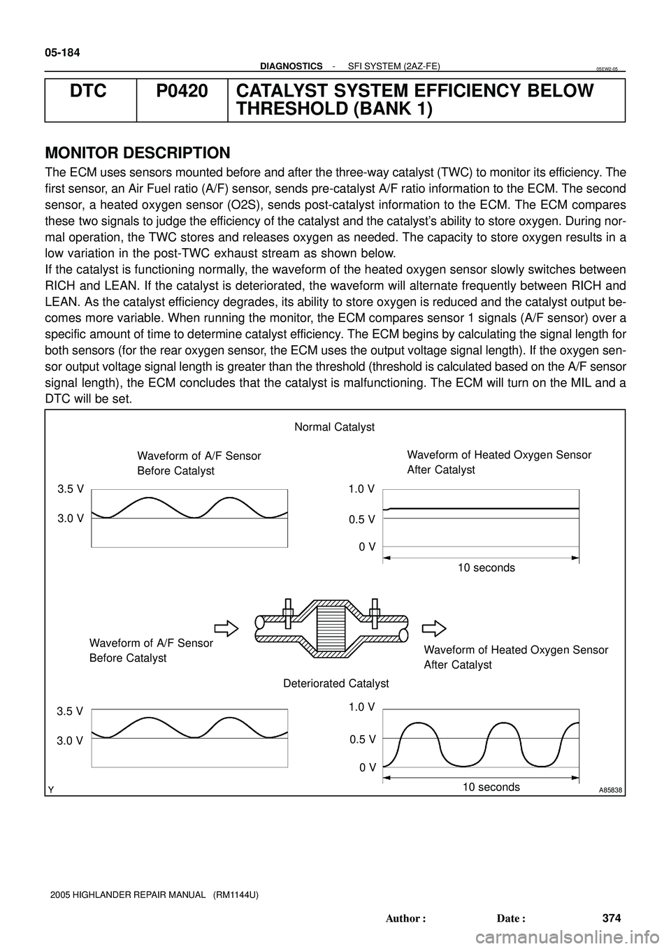
low variation in the post-TWC exhaust stream as shown below.
If the catalyst is functioning normally, the waveform of the heated oxygen sensor slowly switches between
RICH and LEAN. If the catalyst is deteriorated, the waveform will alternate frequently between RICH and
LEAN. As the catalyst efficiency degrades, its ability to store oxygen is reduced and the catalyst output be-
comes more variable. When running the monitor, the ECM compares sensor 1 signals (A/F sensor) over a
specific amount of time to determine catalyst efficiency. The ECM begins by calculating the signal length for
both sensors (for the rear oxygen sensor, the ECM uses the output voltage signal length). If the oxygen sen-
sor output voltage signal length is greater than the threshold (threshold is calculated based on the A/F sensor
signal length), the ECM concludes that the catalyst is malfunctioning. The ECM will turn on the MIL and a
DTC will be set.
05EW2-05
Page 1772 of 2572
A76973
ECM
Fuel Tank
Charcoal
Canister EVAP VSV
Vapor Pressure
Sensor
CCV EVAP Service
PortIntake Air
Throttle
Valve
Fuel Tank Cap
Air Cleaner Case
Charcoal Canister Filter Charcoal Filter
Intake Manifold
Purge Line
Air Inlet Line EVAP Line Purge Line
Diaphragm
(Atmospheric Pressure)
Restrictor
Passage
When EVAP VSV is opened, partial vacuum is created
When CCV is
opened, air is
drawn or released
Leak Detection Area
(Purge Valve)
Air Cleaner Filter
- DIAGNOSTICSSFI SYSTEM (3MZ-FE)
05-565
755 Author�: Date�:
2005 HIGHLANDER REPAIR MANUAL (RM1144U)
Page 1790 of 2572
A76973
ECM
Fuel Tank
Charcoal
Canister EVAP VSV
Vapor Pressure
Sensor
CCV EVAP Service
PortIntake Air
Throttle
Valve
Fuel Tank Cap
Air Cleaner Case
Charcoal Canister Filter Charcoal Filter
Intake Manifold
Purge Line
Air Inlet Line EVAP Line Purge Line
Diaphragm
(Atmospheric Pressure)
Restrictor
Passage
When VSV for EVAP is opened, partial vacuum is created
When CCV is
opened, air is
drawn or released
Leak Detection Area
Fig. 1
(purge valve) 05-574
- DIAGNOSTICSSFI SYSTEM (3MZ-FE)
764 Author�: Date�:
2005 HIGHLANDER REPAIR MANUAL (RM1144U)