Page 980 of 2572

A53766
E7
E8E9 E6E5
05-2068
- DIAGNOSTICSMULTIPLEX COMMUNICATION SYSTEM
2258 Author�: Date�:
2005 HIGHLANDER REPAIR MANUAL (RM1144U)
(1) Disconnect the connectors of the meter assy, ECM and body ECU.
(2) Inspect the continuity between terminals E6-18 (MPX1) of the ECM vehicle's side connector and
B10-6 (MPX1) of the body ECU vehicle's side connector.
Standard:
Symbols (Terminal No.)Specified Condition
MPX1 (E6-18) @ MPX1 (B10-6)
(equipped with 1MZ-FE)Continuity
MPX1 (E6-18) @ MPX1 (B10-6)
(equipped with 2AZ-FE)Continuity
(3) Inspect the continuity between terminals E6-29 (MPX2) of the ECM vehicle's side connector and
C12-9 (MPX+) of the meter assy vehicle's side connector.
Standard:
Symbols (Terminal No.)Specified Condition
MPX2 (E6-29) @ MPX+ (C12-9)
(equipped with 1MZ-FE)Continuity
MPX2 (E6-29) @ MPX+ (C12-9)
(equipped with 2AZ-FE)Continuity
NG REPAIR OR REPLACE HARNESS AND
CONNECTOR
OK
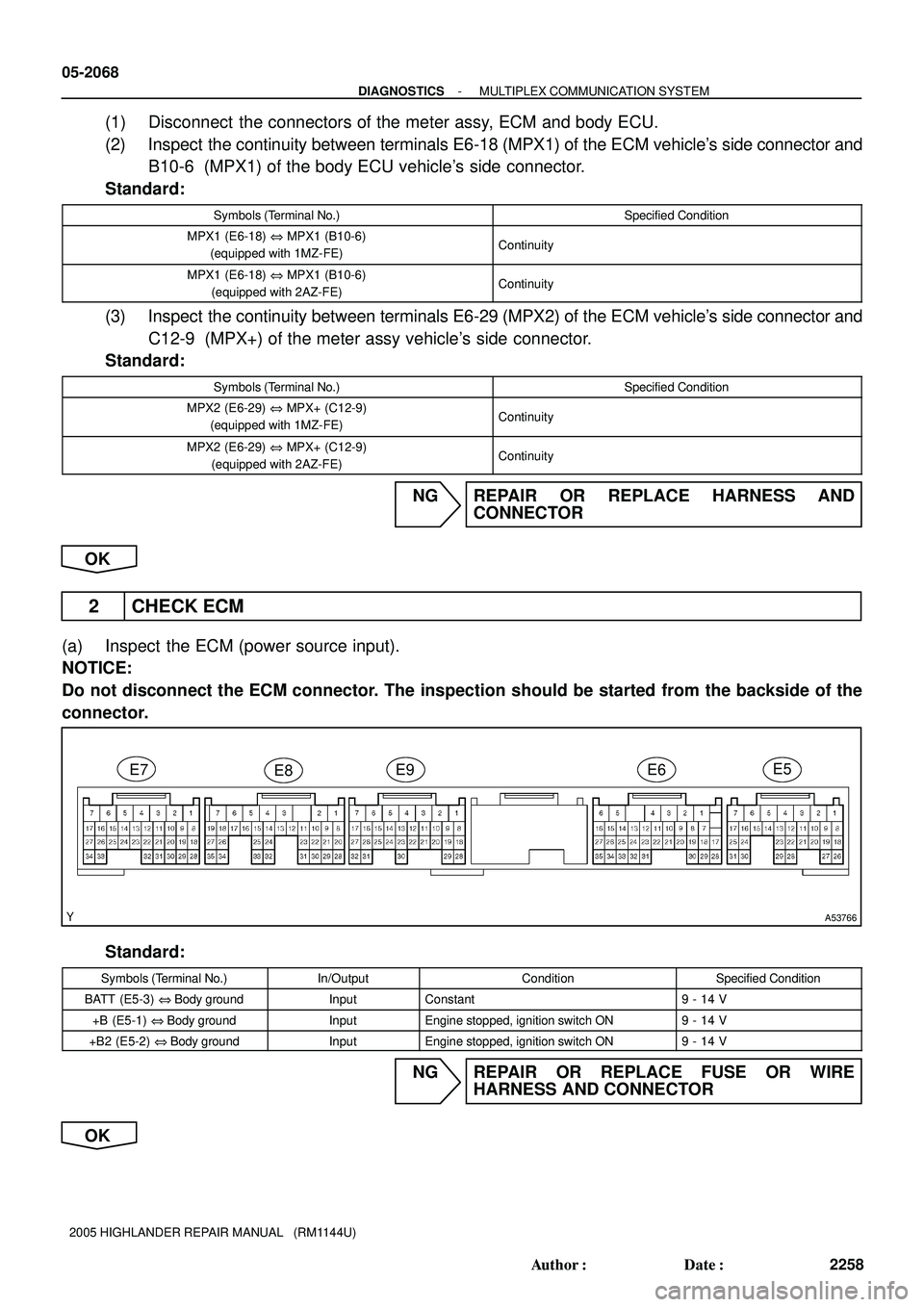
2 CHECK ECM
(a) Inspect the ECM (power source input).
NOTICE:
Do not disconnect the ECM connector. The inspection should be started from the backside of the
connector.
Standard:
Symbols (Terminal No.)In/OutputConditionSpecified Condition
BATT (E5-3) @ Body groundInputConstant9 - 14 V
+B (E5-1) @ Body groundInputEngine stopped, ignition switch ON9 - 14 V
+B2 (E5-2) @ Body groundInputEngine stopped, ignition switch ON9 - 14 V
NG REPAIR OR REPLACE FUSE OR WIRE
HARNESS AND CONNECTOR
OK
Page 991 of 2572

B51838
C11
- DIAGNOSTICSMULTIPLEX COMMUNICATION SYSTEM
05-2083
2273 Author�: Date�:
2005 HIGHLANDER REPAIR MANUAL (RM1144U)
(1) Disconnect the connectors of the meter assy, ECM and air conditioner amplifier.
(2) Inspect the continuity between terminal C12-9 (MPX+) of the meter assy vehicle's side connec-
tor and terminal E6-29 (MPX2) of the ECM vehicle's side connector.
Standard:
Symbols (Terminal No.)Specified Condition
MPX+ (C12-9) @ MPX2 (E6-29)
(equipped with 1MZ-FE)Continuity
MPX+ (C12-9) @ MPX2 (E6-29)
(equipped with 2AZ-FE)Continuity
(3) Inspect the continuity between terminal C11-21 (MPX-) of the meter assy vehicle's side connec-
tor and terminal A10-9 (MPX-) of the air conditioner amplifier vehicle's side connector.
Standard: Continuity
NG REPAIR OR REPLACE HARNESS AND
CONNECTOR
OK
2 CHECK COMBINATION METER ASSY
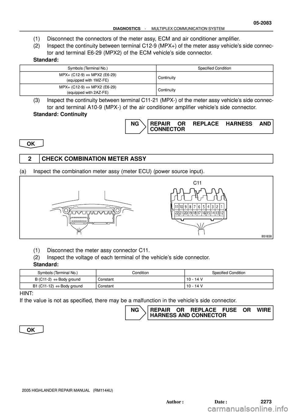
(a) Inspect the combination meter assy (meter ECU) (power source input).
(1) Disconnect the meter assy connector C11.
(2) Inspect the voltage of each terminal of the vehicle's side connector.
Standard:
Symbols (Terminal No.)ConditionSpecified Condition
B (C11-2) @ Body groundConstant10 - 14 V
B1 (C11-12) @ Body groundConstant10 - 14 V
HINT:
If the value is not as specified, there may be a malfunction in the vehicle's side connector.
NG REPAIR OR REPLACE FUSE OR WIRE
HARNESS AND CONNECTOR
OK
Page 1260 of 2572

B51840
S20
05-2088
- DIAGNOSTICSMULTIPLEX COMMUNICATION SYSTEM
2278 Author�: Date�:
2005 HIGHLANDER REPAIR MANUAL (RM1144U)
(1) Disconnect the connectors of the sliding roof ECU, ECM and meter assy.
(2) Inspect the continuity between terminal S20-10 (MPX1) of the sliding roof ECU vehicle's side
connector and terminal E6-29 (MPX2) of the ECM vehicle's side connector.
Standard:
Symbols (Terminal No.)Specified Condition
MPX1 (S20-10) @ MPX2 (E6-29)
(equipped with 1MZ-FE)Continuity
MPX1 (S20-10) @ MPX2 (E6-29)
(equipped with 2AZ-FE)Continuity
(3) Inspect the continuity between terminal S20-10 (MPX1) of the sliding roof ECU vehicle's side
connector and terminal C12-9 (MPX+) of the meter assy vehicle's side connector.
Standard: Continuity
NG REPAIR OR REPLACE HARNESS AND
CONNECTOR
OK
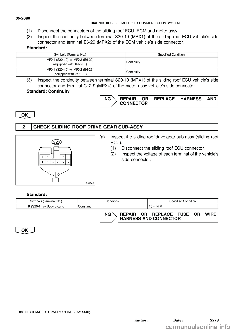
2 CHECK SLIDING ROOF DRIVE GEAR SUB-ASSY
(a) Inspect the sliding roof drive gear sub-assy (sliding roof
ECU).
(1) Disconnect the sliding roof ECU connector.
(2) Inspect the voltage of each terminal of the vehicle's
side connector.
Standard:
Symbols (Terminal No.)ConditionSpecified Condition
B (S20-1) @ Body groundConstant10 - 14 V
NG REPAIR OR REPLACE FUSE OR WIRE
HARNESS AND CONNECTOR
OK