Page 1379 of 2572

05IS7-02
I38587*1
*2*1
*2*3
*4
05-1768
- DIAGNOSTICSNAVIGATION SYSTEM
1958 Author�: Date�:
2005 HIGHLANDER REPAIR MANUAL (RM1144U)
DIAGNOSIS DISPLAY DETAILED DESCRIPTION
HINT:
�This section contains a detailed description of displays within diagnostic mode.
�Illustrations may differ from the actual vehicle depending on the device settings and options. There-
fore, some detailed areas may not be shown exactly the same as on the actual vehicle.
1. System Check
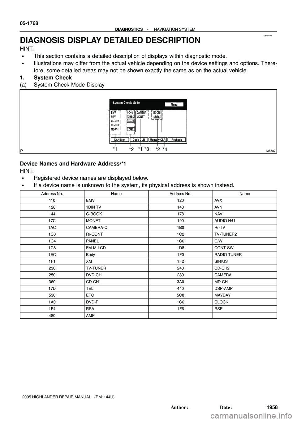
(a) System Check Mode Display
Device Names and Hardware Address/*1
HINT:
�Registered device names are displayed below.
�If a device name is unknown to the system, its physical address is shown instead.
Address No.NameAddress No.Name
11 0EMV120AV X
1281DIN TV140AV N
144G-BOOK178NAVI
17CMONET190AUDIO H/U
1ACCAMERA-C1B0Rr-TV
1C0Rr-CONT1C2TV-TUNER2
1C4PANEL1C6G/W
1C8FM-M-LCD1D8CONT-SW
1ECBody1F0RADIO TUNER
1F1XM1F2SIRIUS
230TV-TUNER240CD-CH2
250DVD-CH280CAMERA
360CD-CH13A0MD-CH
17DTEL440DSP-AMP
530ETC5C8MAYDAY
1A0DVD-P1C6CLOCK
1F4RSA1F6RSE
480AMP
Page 2029 of 2572

B51847
Driving Axis
ClockwiseCounterclock-
wise
- DIAGNOSTICSPOWER WINDOW CONTROL SYSTEM
05-1919
2109 Author�: Date�:
2005 HIGHLANDER REPAIR MANUAL (RM1144U)
5 INSPECT POWER WINDOW REGULATOR MOTOR ASSY LH (DRIVER SIDE)
(a) Inspect the power window regulator motor assy LH (Driver side) operation.
NOTICE:
�Do not apply the battery voltage, because the pulse sensor and limit switch could be damaged
if the battery voltage is applied to terminals 2, 3 and 6 of the power window regulator motor con-
nector.
�Be sure to reset the power window regulator motor (initial position setting of limit switch) when
the driver's side power window regulator motor is installed to the regulator.
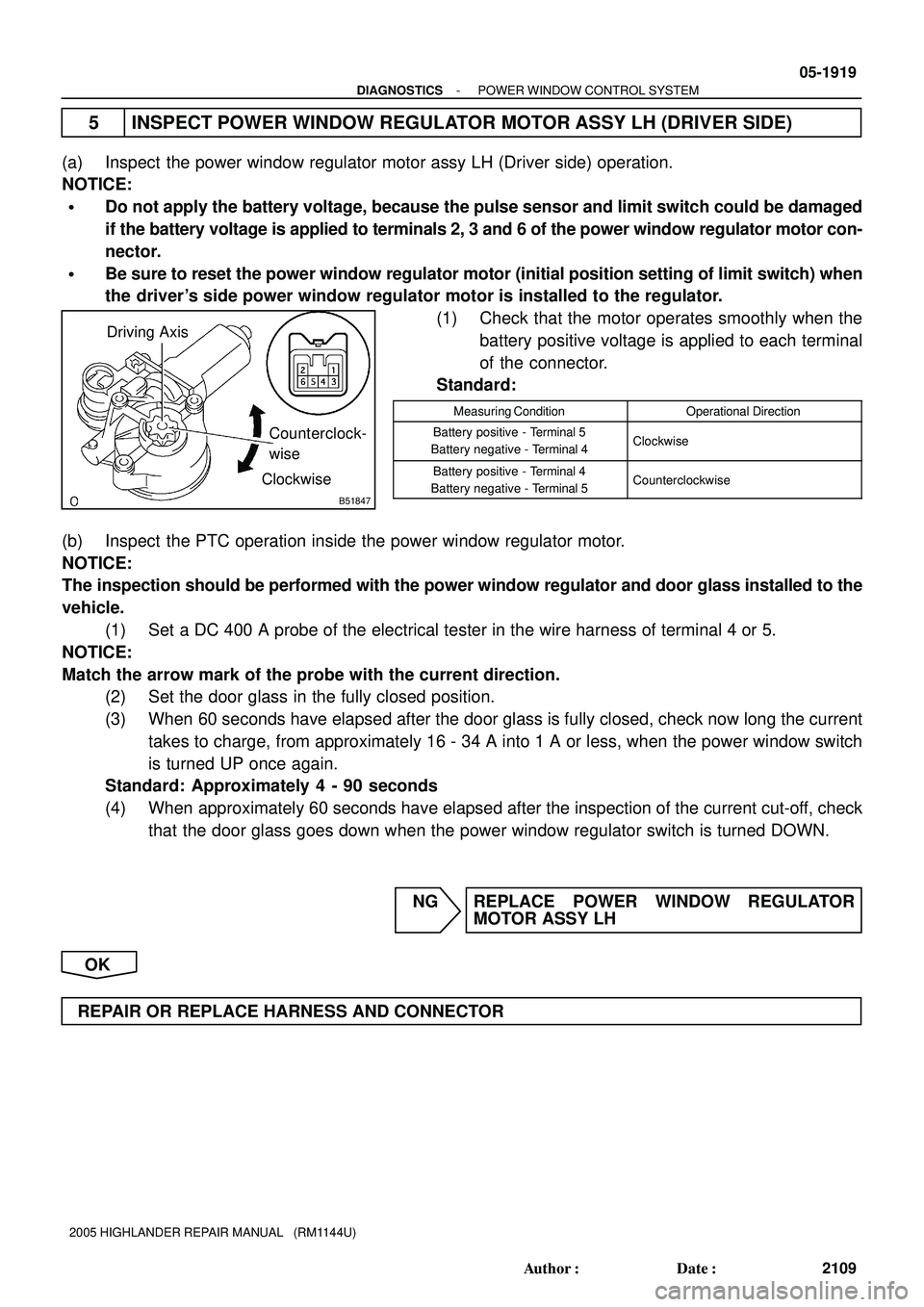
(1) Check that the motor operates smoothly when the
battery positive voltage is applied to each terminal
of the connector.
Standard:
Measuring ConditionOperational Direction
Battery positive - Terminal 5
Battery negative - Terminal 4Clockwise
Battery positive - Terminal 4
Battery negative - Terminal 5Counterclockwise
(b) Inspect the PTC operation inside the power window regulator motor.
NOTICE:
The inspection should be performed with the power window regulator and door glass installed to the
vehicle.
(1) Set a DC 400 A probe of the electrical tester in the wire harness of terminal 4 or 5.
NOTICE:
Match the arrow mark of the probe with the current direction.
(2) Set the door glass in the fully closed position.
(3) When 60 seconds have elapsed after the door glass is fully closed, check now long the current
takes to charge, from approximately 16 - 34 A into 1 A or less, when the power window switch
is turned UP once again.
Standard: Approximately 4 - 90 seconds
(4) When approximately 60 seconds have elapsed after the inspection of the current cut-off, check
that the door glass goes down when the power window regulator switch is turned DOWN.
NG REPLACE POWER WINDOW REGULATOR
MOTOR ASSY LH
OK
REPAIR OR REPLACE HARNESS AND CONNECTOR
Page 2225 of 2572

D25080
Negative (-)
Terminal
D31751
INCORRECT
- INTRODUCTIONREPAIR INSTRUCTION
01-15
15 Author�: Date�:
2005 HIGHLANDER REPAIR MANUAL (RM1144U)
(i) WIRE HARNESS AND CONNECTOR
(1) The SRS wire harness is integrated with the instrument panel wire harness assembly. All the con-
nectors in the system are a standard yellow color. If the SRS wire harness becomes discon-
nected or the connector becomes broken, repair or replace it.
2. ELECTRONIC CONTROL
(a) REMOVAL AND INSTALLATION OF BATTERY TERMI-
NAL
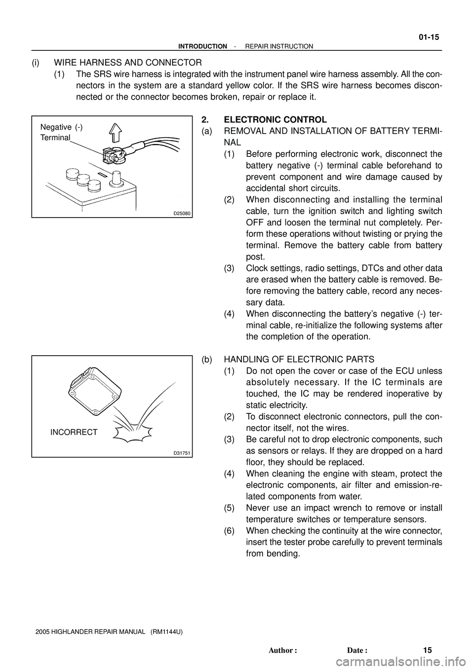
(1) Before performing electronic work, disconnect the
battery negative (-) terminal cable beforehand to
prevent component and wire damage caused by
accidental short circuits.
(2) When disconnecting and installing the terminal
cable, turn the ignition switch and lighting switch
OFF and loosen the terminal nut completely. Per-
form these operations without twisting or prying the
terminal. Remove the battery cable from battery
post.
(3) Clock settings, radio settings, DTCs and other data
are erased when the battery cable is removed. Be-
fore removing the battery cable, record any neces-
sary data.
(4) When disconnecting the battery's negative (-) ter-
minal cable, re-initialize the following systems after
the completion of the operation.
(b) HANDLING OF ELECTRONIC PARTS
(1) Do not open the cover or case of the ECU unless
absolutely necessary. If the IC terminals are
touched, the IC may be rendered inoperative by
static electricity.
(2) To disconnect electronic connectors, pull the con-
nector itself, not the wires.
(3) Be careful not to drop electronic components, such
as sensors or relays. If they are dropped on a hard
floor, they should be replaced.
(4) When cleaning the engine with steam, protect the
electronic components, air filter and emission-re-
lated components from water.
(5) Never use an impact wrench to remove or install
temperature switches or temperature sensors.
(6) When checking the continuity at the wire connector,
insert the tester probe carefully to prevent terminals
from bending.
Page 2387 of 2572

71-2
- INSTRUMENT PANEL/METERCOMBINATION METER
3593 Author�: Date�:
MAINT REQD indicator ia blinking or cotinuously illuminated.1. Resetting procedure
2. Combination Meter Assy71-3
71-18
All buzzer (key reminder, tail cancel, Seat belt) does not operate.1. Refer to troubleshooting
2. Combination Meter Assy05-1879
71-18
O/D OFF indicator light does not come on.
1. O/D off Select Switch
2. Wire Harness or Connector
3. Combination Meter Assy-
-
71-18
SLIP indicator light does not come on.
1. Wire Harness or Connector
2. Skid Control ECU
3. Combination Meter Assy-
05-761
71-18
VSC indicator light does not come on.
1. Wire Harness or Connector
2. Skid Control ECU
3. Combination Meter Assy-
05-761
71-18
TRC/TRAC OFF indicator light does not come on.
1. Wire Harness or Connector
2. Skid Control ECU
3. Combination Meter Assy-
05-761
71-18
A/T OIL TEMP indicator light does not come on.
1. Wire Harness or Connector
2. Automatic transmission
3. Combination Meter Assy-
05-883
05-993
71-18
ECT SNOW indicator light does not come on.
1. Wire Harness or Connector
2. ECM
3. Combination Meter Assy-
05-5
05-366
71-18
A/T shift indicator light does not come on.
1. Park Neutral Position Switch
2. Wire Harness or Connector
3. ECM
4. Combination Meter Assy05-883
05-993
-
05-5
05-366
71-18
ºCRUISEº indicator light does not come on.
1. Wire Harness or Connector
2. ECM
3. Combination Meter Assy-
05-5
05-366
71-18
Meter Gauges:
SymptomSuspect AreaSee page
Speedometer does not operate.1. Refer to troubleshooting05-1885
Tachometer does not operate.1. Refer to troubleshooting05-1889
Fuel Gauge does not operate or operates abnormally.1. Refer to troubleshooting05-1893
Water temperature does not operate.1. Refer to troubleshooting05-1896
Clock:
SymptomSuspect AreaSee page
Clock will not operate
Clock loses or gains time
1. Power source or ground
2. Integration control & panel assy05-1 170
05-1 173
05-1 175
71-6