Page 746 of 2572

S27
BRL
- DIAGNOSTICSABS WITH EBD & BA & TRAC & VSC SYSTEM
05-855
1045 Author�: Date�:
INSPECTION PROCEDURE
HINT:
When releasing the parking brake, se")
G24767
Skid Control ECU
(harness side connector)
S27
BRL
- DIAGNOSTICSABS WITH EBD & BA & TRAC & VSC SYSTEM
05-855
1045 Author�: Date�:
INSPECTION PROCEDURE
HINT:
When releasing the parking brake, set the chocks to hold the vehicle for safety.
1 CHECK BRAKE FLUID
(a) Release the parking brake pedal.
(b) Check that the brake fluid level is proper.
NG ADD BRAKE FLUID
OK
2 CHECK DTC FOR ABS
(a) Are the DTC recorded? (see page 05-765)
NO Go to step 3
YES
REPAIR CIRCUIT INDICATED BY OUTPUT CODE
3 INSPECT BRAKE WARNING LIGHT
WHEN USING HAND-HELD TESTER:
(a) Connect the hand-held tester to the DLC3.
(b) Start the engine.
(c) Select the item ºBRAKE WARN LIGHTº in the ACTIVE TEST and operate the BRAKE warning light
on the hand-held tester.
ItemVehicle Condition / Test DetailsDiagnostic Note
BRAKE WRN LIGHTTurns BRAKE warning light ON / OFFObserve combination me-
ter
(d) Check that ºONº and ºOFFº of the BRAKE warning light are indicated on the combination meter when
using the hand-held tester.
OK:
Turn the BRAKE warning light on or off in accordance with the hand-held tester.
WHEN NOT USING HAND-HELD TESTER:
(a) Turn the ignition switch off and disconnect the connector
from the skid control ECU.
(b) Ground terminal BRL of the skid control ECU.
(c) Turn the ignition switch to the ON position.
(d) Check that the brake warning light.
OK:
Turn the light on or off in accordance with the connec-
tion of terminal BRL and body ground.
NG Go to step 4
OK
REPLACE ABS & TRACTION ACTUATOR ASSY (SEE PAGE 32-37)
Page 773 of 2572
C93876
21
A4 A5
Front Speed Sensor
- DIAGNOSTICSABS WITH EBD & BA & TRAC & VSC SYSTEM
05-791
981 Author�: Date�:
3 INSPECT FRONT SPEED SENSOR
(a) Make sure that there is no looseness at the connectors'
locking part and connecting part of connector.
(b) Disconnect the speed sensor connector.
(c) Measure the resistance according to the value(s) in the
table below.
Standard:
LH:
Tester ConnectionSpecified Condition
A4-1 (FL-) - A4-2 (FL+)0.6 to 2.5 kW
RH:
Tester ConnectionSpecified Condition
A5-1 (FR-) - A5-2 (FR+)0.6 to 2.5 kW
(d) Measure the resistance according to the value(s) in the
table below.
Standard:
LH:
Tester ConnectionSpecified Condition
A4-1 (FL-) - Body ground10 kW or higher
A4-2 (FL+) - Body ground10 kW or higher
RH:
Tester ConnectionSpecified Condition
A5-1 (FR-) - Body ground10 kW or higher
A5-2 (FR+) - Body ground10 kW or higher
NOTICE:
Check the speed sensor signal after replacement
(see page 05-765).
NG REPLACE FRONT SPEED SENSOR
(SEE PAGE 32-40)
OK
Page 775 of 2572

No Clearance
- DIAGNOSTICSABS WITH EBD & BA & TRAC & VSC SYSTEM
05-793
983 Autho")
W04200
Normal Signal Waveform
1 V / Division2 m/s / DivisionGND
BR3795OKNG Speed Sensor
8.0 NVm
(82 kgfVcm, 71 in.Vlbf)
No Clearance
- DIAGNOSTICSABS WITH EBD & BA & TRAC & VSC SYSTEM
05-793
983 Author�: Date�:
5 INSPECT SPEED SENSOR AND SENSOR ROTOR SERRATIONS
INSPECTION USING OSCILLOSCOPE
(a) Connect the oscilloscope to terminal FR+ - FR- or FL+
- FL- of the skid control ECU.
(b) Drive the vehicle at about 19 mph (30 km/h), and check
the signal waveform.
OK:
A waveform as shown in a figure should be output.
HINT:
�As the vehicle speed (wheel revolution speed) increases,
a cycle of the waveform narrows and the fluctuation in the
output voltage becomes greater.
�When noise is identified in the waveform on the oscillo-
scope, error signals are generated due to the speed sen-
sor rotor's scratches, looseness or foreign matter at-
tached to it.
NG Go to step 6
OK
REPLACE ABS & TRACTION ACTUATOR ASSY (SEE PAGE 32-37)
6 INSPECT FRONT SPEED SENSOR INSTALLATION
(a) Check the speed sensor installation.
OK:
� The installation bolt is tightened properly.
Torque: 8.0 NVm (82 kgfVcm, 71 in.Vlbf)
� There is no clearance between the sensor and the
front steering knuckle.
NOTICE:
Check the speed sensor signal after the replacement
(see page 05-765).
NG REPLACE FRONT SPEED SENSOR
(SEE PAGE 32-40)
OK
Page 776 of 2572
R00948
Speed Sensor Rotor
05-794
- DIAGNOSTICSABS WITH EBD & BA & TRAC & VSC SYSTEM
984 Author�: Date�:
7 INSPECT SPEED SENSOR TIP
(a) Remove the front speed sensor (see page 32-40).
(b) Check the sensor tip.
OK:
No scratches or foreign matter on the sensor tip.
NOTICE:
Check the speed sensor signal after the replacement (see page 05-765).
NG CLEAN OR REPAIR SPEED SENSOR
OK
8 INSPECT SPEED SENSOR ROTOR
(a) Remove the front speed sensor rotor.
(b) Check the sensor rotor serrations.
OK:
No scratches, missing teeth or foreign matter on the
rotors.
HINT:
If there is foreign matter in the rotor, remove it and check the
output waveform after reassembly.
NOTICE:
Check the speed sensor signal after the replacement
(see page 05-765).
NG CLEAN OR REPAIR SPEED SENSOR ROTOR
OK
REPLACE ABS & TRACTION ACTUATOR ASSY (SEE PAGE 32-37)
Page 780 of 2572

Skid Control Sensor
(harness side connector)S27
A24
A25
RR+
RR+ RR- RR-
RL+
RL-RL-
RL+
05-798
- DIAGNOSTICSABS WITH EBD & BA & TRAC & VSC S")
R14205
1
2
G26241
Skid Control ECU
(harness side connector)
Skid Control Sensor
(harness side connector)S27
A24
A25
RR+
RR+ RR- RR-
RL+
RL-RL-
RL+
05-798
- DIAGNOSTICSABS WITH EBD & BA & TRAC & VSC SYSTEM
988 Author�: Date�:
4WD:
(a) Disconnect the rear speed sensor connector.
(b) Measure the resistance according to the value(s) in the
table below.
Standard:
Tester ConnectionSpecified Condition
1 - 20.9 to 1.3 kW at 25 �C
(c) Measure the resistance according to the value(s) in the
table below.
Standard:
Tester ConnectionSpecified Condition
1 - Body ground10 kW or higher
2 - Body ground10 kW or higher
NOTICE:
Check the speed sensor signal after replacement
(see page 05-765).
NG REPLACE REAR SPEED SENSOR
(SEE PAGE 32-37)
OK
4 CHECK HARNESS AND CONNECTOR(REAR SPEED SENSOR - SKID CONTROL
ECU)
(a) Disconnect the skid control ECU connector and the skid
control sensor connector.
(b) Measure the resistance according to the value(s) in the
table below.
Standard:
LH:
Tester ConnectionSpecified Condition
S27-20 (RL+) - A24-1 (RL+)Below 1 W
S27-6 (RL-) - A24-2 (RL-)Below 1 W
RH:
Tester ConnectionSpecified Condition
S27-5 (RR+) - A25-1 (RR+)Below 1 W
S27-19 (RR-) - A25-2 (RR-)Below 1 W
(c) Measure the resistance according to the value(s) in the
table below.
Standard:
LH:
Tester ConnectionSpecified Condition
S27-20 (RL+) - Body ground10 kW or higher
S27-6 (RL-) - Body ground10 kW or higher
RH:
Tester ConnectionSpecified Condition
S27-5 (RR+) - Body ground10 kW or higher
S27-19 (RR-) - Body ground10 kW or higher
Page 782 of 2572
F10178
OK
NG Skid Control Sensor
BR3795OKNG
8.0 NVm
(82 kgfVcm,71 in.Vlbf)
No Clearnace
05-800
- DIAGNOSTICSABS WITH EBD & BA & TRAC & VSC SYSTEM
990 Author�: Date�:
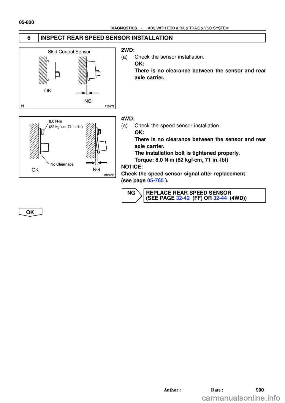
6 INSPECT REAR SPEED SENSOR INSTALLATION
2WD:
(a) Check the sensor installation.
OK:
There is no clearance between the sensor and rear
axle carrier.
4WD:
(a) Check the speed sensor installation.
OK:
There is no clearance between the sensor and rear
axle carrier.
The installation bolt is tightened properly.
Torque: 8.0 NVm (82 kgfVcm, 71 in.Vlbf)
NOTICE:
Check the speed sensor signal after replacement
(see page 05-765).
NG REPLACE REAR SPEED SENSOR
(SEE PAGE 32-42 (FF) OR 32-44 (4WD))
OK
Page 783 of 2572
F08575
Sensor Rotor
R00948
Sensor Rotor
- DIAGNOSTICSABS WITH EBD & BA & TRAC & VSC SYSTEM
05-801
991 Author�: Date�:
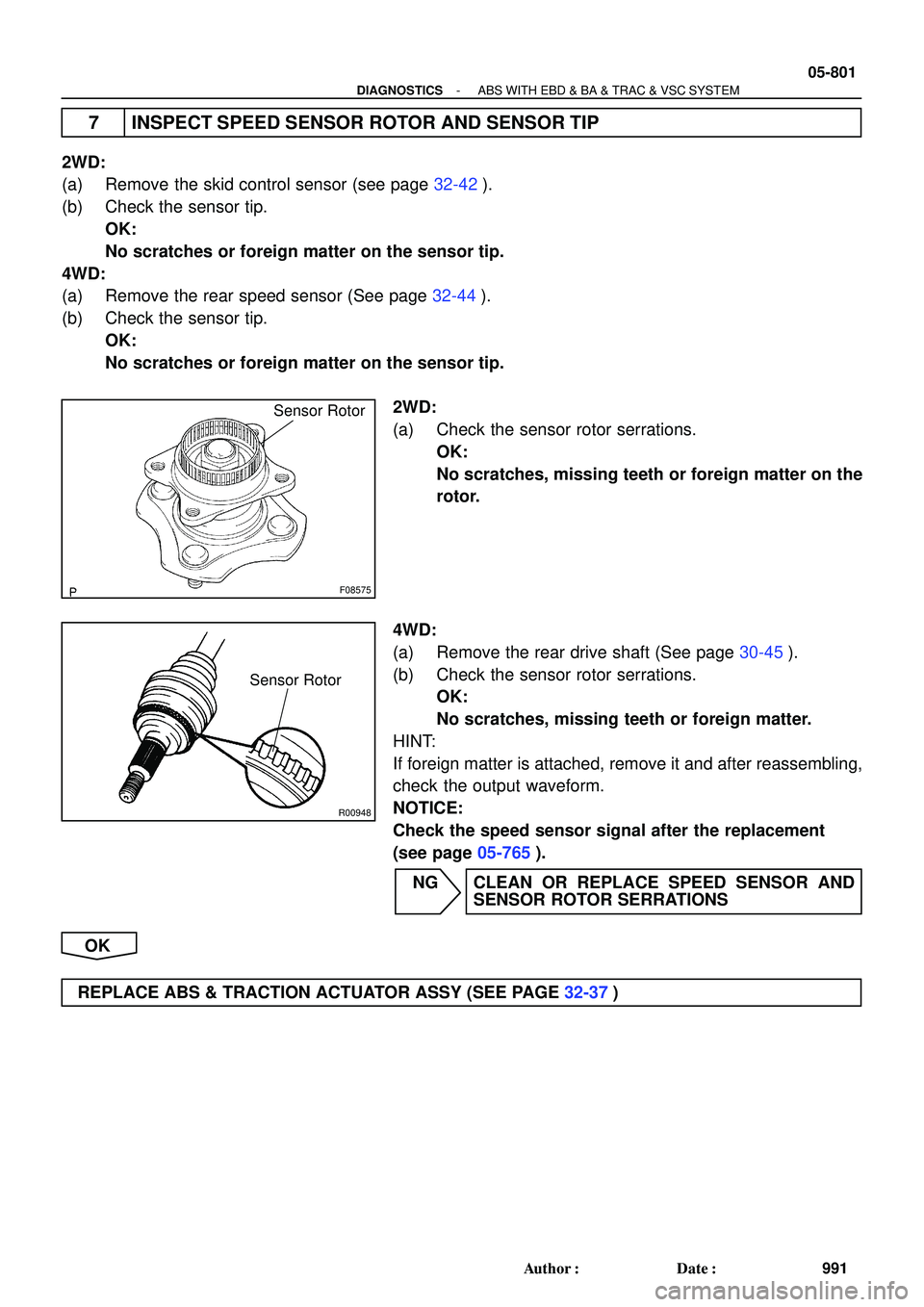
7 INSPECT SPEED SENSOR ROTOR AND SENSOR TIP
2WD:
(a) Remove the skid control sensor (see page 32-42).
(b) Check the sensor tip.
OK:
No scratches or foreign matter on the sensor tip.
4WD:
(a) Remove the rear speed sensor (See page 32-44).
(b) Check the sensor tip.
OK:
No scratches or foreign matter on the sensor tip.
2WD:
(a) Check the sensor rotor serrations.
OK:
No scratches, missing teeth or foreign matter on the
rotor.
4WD:
(a) Remove the rear drive shaft (See page 30-45).
(b) Check the sensor rotor serrations.
OK:
No scratches, missing teeth or foreign matter.
HINT:
If foreign matter is attached, remove it and after reassembling,
check the output waveform.
NOTICE:
Check the speed sensor signal after the replacement
(see page 05-765).
NG CLEAN OR REPLACE SPEED SENSOR AND
SENSOR ROTOR SERRATIONS
OK
REPLACE ABS & TRACTION ACTUATOR ASSY (SEE PAGE 32-37)
Page 785 of 2572
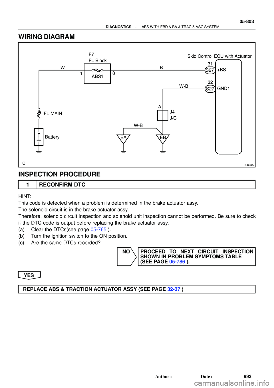
F46309
Skid Control ECU with Actuator F7
FL Block
FL MAIN
Battery
EA EB ABS1+BS
GND1
J4
J/C 1831
32
AB W
W-BS27
S27 W-B
- DIAGNOSTICSABS WITH EBD & BA & TRAC & VSC SYSTEM
05-803
993 Author�: Date�:
WIRING DIAGRAM
INSPECTION PROCEDURE
1 RECONFIRM DTC
HINT:
This code is detected when a problem is determined in the brake actuator assy.
The solenoid circuit is in the brake actuator assy.
Therefore, solenoid circuit inspection and solenoid unit inspection cannot be performed. Be sure to check
if the DTC code is output before replacing the brake actuator assy.
(a) Clear the DTCs(see page 05-765).
(b) Turn the ignition switch to the ON position.
(c) Are the same DTCs recorded?
NO PROCEED TO NEXT CIRCUIT INSPECTION
SHOWN IN PROBLEM SYMPTOMS TABLE
(SEE PAGE 05-786).
YES
REPLACE ABS & TRACTION ACTUATOR ASSY (SEE PAGE 32-37)