Page 792 of 2572
S27
05-810
- DIAGNOSTICSABS WITH EBD & BA & TRAC & VSC SYSTEM
1000 Author�: Date�:
INSPECTION PROCEDURE
1 INSPECT FUSE(AB")
F40458
ABS1 FL BLOCK
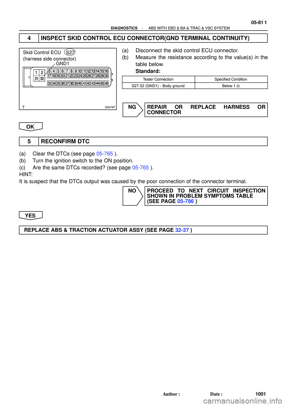
G24767
GND1
+BS Skid Control ECU
(harness side connector)S27
05-810
- DIAGNOSTICSABS WITH EBD & BA & TRAC & VSC SYSTEM
1000 Author�: Date�:
INSPECTION PROCEDURE
1 INSPECT FUSE(ABS1 FUSE)
(a) Remove ABS1 fuse from the FL BLOCK.
(b) Check continuity of ABS1 fuse.
Standard:
ABS No.2 fuseBelow 1 W (Continuity)
NG CHECK FOR SHORT IN ALL HARNESS AND
CONNECTOR CONNECTED TO FUSE AND
REPLACE FUSE
OK
2 INSPECT SKID CONTROL ECU CONNECTOR(+BS TERMINAL VOLTAGE)
(a) Disconnect the skid control ECU connector.
(b) Turn the ignition switch to the ON position.
(c) Measure the voltage according to the value(s) in the table
below.
Standard:
Tester ConnectionSpecified Condition
S27-31 (+BS) - S27-32 (GND1)10 to 14 V
NG Go to step 4
OK
3 RECONFIRM DTC
(a) Clear the DTCs (see page 05-765).
(b) Turn the ignition switch to the ON position.
(c) Are the same DTCs recorded?
NOTICE:
When replacing ABS & TRACTION ACTUATOR ASSY, perform zero point calibration
(see page 05-765).
NO PROCEED TO NEXT CIRCUIT INSPECTION
SHOWN IN PROBLEM SYMPTOMS TABLE
(SEE PAGE 05-786)
YES
REPLACE ABS & TRACTION ACTUATOR ASSY (SEE PAGE 32-37)
Page 793 of 2572
G24767
GND1
Skid Control ECU
(harness side connector)S27
- DIAGNOSTICSABS WITH EBD & BA & TRAC & VSC SYSTEM
05-81 1
1001 Author�: Date�:
4 INSPECT SKID CONTROL ECU CONNECTOR(GND TERMINAL CONTINUITY)
(a) Disconnect the skid control ECU connector.
(b) Measure the resistance according to the value(s) in the
table below.
Standard:
Tester ConnectionSpecified Condition
S27-32 (GND1) - Body groundBelow 1 W
NG REPAIR OR REPLACE HARNESS OR
CONNECTOR
OK
5 RECONFIRM DTC
(a) Clear the DTCs (see page 05-765).
(b) Turn the ignition switch to the ON position.
(c) Are the same DTCs recorded? (see page 05-765).
HINT:
It is suspect that the DTCs output was caused by the poor connection of the connector terminal.
NO PROCEED TO NEXT CIRCUIT INSPECTION
SHOWN IN PROBLEM SYMPTOMS TABLE
(SEE PAGE 05-786)
YES
REPLACE ABS & TRACTION ACTUATOR ASSY (SEE PAGE 32-37)
Page 798 of 2572
05-816
- DIAGNOSTICSABS WITH EBD & BA & TRAC & VSC SYSTEM
1006 Author�: Date�:
INSPECTION PROCEDURE
HINT:
When U0121/94, U0123/62, U0124/95 or U0126/63 are output accompanied with C1210/36 or C1336/39,
inspect and repair the trouble areas indicated by U0121/94, U0123/62, U0124/95 or U0126/63 first.
1 PERFORM ZERO POINT CALIBRATION OF YAW RATE SENSOR AND
DECELERATION SENSOR
(a) Perform the zero point calibration of the yaw rate sensor and deceleration sensor
(see page 05-765).
NEXT
2 RECONFIRM DTC
(a) Clear the DTCs (see page 05-765).
(b) Turn the ignition switch to the ON position.
(c) Are the same DTCs recorded? (see page 05-765).
NO PROCEED TO NEXT CIRCUIT INSPECTION
SHOWN IN PROBLEM SYMPTOMS TABLE
(SEE PAGE 05-786)
YES
3 CHECK SENSOR INSTALLATION
(a) Check that the yaw rate sensor has been installed properly (see page 32-46).
NG INSTALL YAW RATE SENSOR CORRECTLY
OK
REPLACE YAWRATE SENSOR(SEE PAGE 32-46)
Page 799 of 2572
- DIAGNOSTICSABS WITH EBD & BA & TRAC & VSC SYSTEM
05-817
1007 Author�: Date�:
DTC C1223/43 ABS CONTROL SYSTEM MALFUNCTION
CIRCUIT DESCRIPTION
HINT:
�This DTC is output when the VSC system detects a malfunction in the ABS system.
�When DTC C1223/43 is memorized, there is no malfunction in the skid control ECU.
DTC No.DTC Detecting ConditionTrouble Area
C1223/43Malfunction in ABS control systemABS control system
INSPECTION PROCEDURE
1 CHECK DTC(FOR ABS SYSTEM)
(a) Clear the DTCs (see page 05-765).
(b) Turn the ignition switch to the ON position.
(c) Are the same DTCs recorded? (see page 05-765)
NO PROCEED TO NEXT CIRCUIT INSPECTION
SHOWN IN PROBLEM SYMPTOMS TABLE (SEE
PAGE 05-786)
YES
REPAIR CIRCUIT INDICATED BY OUTPUT DTC
05CD8-07
Page 802 of 2572

G26185
ECM
NEOE5
A20293
4.5 to 14 V
Below 1 V20 V/DIV, 1 ms/DIV Pulse
Generation
05-820
- DIAGNOSTICSABS WITH EBD & BA & TRAC & VSC SYSTEM
1010 Author�: Date�:
2 INSPECT ECM TERMINAL VOLTAGE(NEO TERMINAL)
(a) Reconnect the ECM connector and the skid control ECU
connector.
(b) Check the signal waveform between terminal NEO
(E5-17) of the ECM and body ground for the engine
conditions below.
OK:
Tester ConnectionEngine ConditionSpecified condition
E5-17 (NEO) - Body
groundOFF (Ignition switch ON)4.5 to 14 V or below 1 V
E5-17 (NEO) - Body
groundON (Idling)Pulse generation
(4.5 to 14 V e below 1 V)
NG REPLACE ECM
OK
3 CHECK IF SKID CONTROL ECU CONNECTOR IS SECURELY CONNECTED
NG CONNECT CONNECTOR TO ECU
OK
4 RECONFIRM DTC
(a) Clear the DTCs (see page 05-765).
(b) Turn the ignition switch to the ON position.
(c) Are the same DTCs recorded?
NO PROCEED TO NEXT CIRCUIT INSPECTION
SHOWN IN PROBLEM SYMPTOMS TABLE
(SEE PAGE 05-786)
YES
REPLACE ABS & TRACTION ACTUATOR ASSY(SEE PAGE 32-37)
Page 815 of 2572

S27
- DIAGNOSTICSABS WITH EBD & BA & TRAC & VSC SYSTEM
05-833
1023 Author�: Date�:
INSPECTION PROCEDURE
1 CHECK STOP LAMP SWITCH OPERATION
(a) Chec")
G24767STP Skid Control ECU
(harness side connector)
S27
- DIAGNOSTICSABS WITH EBD & BA & TRAC & VSC SYSTEM
05-833
1023 Author�: Date�:
INSPECTION PROCEDURE
1 CHECK STOP LAMP SWITCH OPERATION
(a) Check that the stop light comes on when the brake pedal is depressed and goes off when the brake
pedal is released.
HINT:
Check the stop lamp bulb as it may have burnt out.
Standard: Stop lamp switch function is normal.
NG Go to step 4
OK
2 INSPECT SKID CONTROL ECU TERMINAL VOLTAGE(STP TERMINAL)
(a) Disconnect the skid control ECU connector.
(b) Measure the voltage according to the value(s) in the table
below.
Standard:
Tester ConnectionSwitch conditionSpecified Condition
S27-27 (STP) -
Body groundBrake pedal depressed8 to 14 V
S27-27 (STP) -
Body groundBrake pedal releasedBelow 1 V
NG Go to step 5
OK
3 RECONFIRM DTC
(a) Clear the DTCs(see page 05-765).
(b) Turn the ignition switch to the ON position.
(c) Are the same DTCs detected? (see page 05-765).
NO PROCEED TO NEXT CIRCUIT INSPECTION
SHOWN IN PROBLEM SYMPTOMS TABLE
(SEE PAGE 05-786)
YES
REPLACE ABS & TRACTION ACTUATOR ASSY (SEE PAGE 32-37)
Page 2062 of 2572
- DIAGNOSTICSTIRE PRESSURE WARNING SYSTEM
05-751
941 Author�: Date�:
2005 HIGHLANDER REPAIR MANUAL (RM1144U)
ABS SYSTEM MALFUNCTION
CIRCUIT DESCRIPTION
The skid control ECU outputs DTCs when a speed sensor malfunction occurs or there is an open in the stop
lamp switch assy circuit of the ABS system. If ABS system has a malfunction, tire pressure warning system
will not function.
INSPECTION PROCEDURE
1 CHECK DIAGNOSTIC TROUBLE CODE OUTPUT
(a) Check that the normal code is output by ABS system (see page 05-765).
OK:
DTC is not output.
NG REPAIR CIRCUIT INDICATED BY OUTPUT
CODE
OK
PROCEED TO NEXT CIRCUIT INSPECTION SHOWN IN PROBLEM SYMPTOMS TABLE
(SEE PAGE 05-740)
05EZ4-02
Page 2066 of 2572
- DIAGNOSTICSTIRE PRESSURE WARNING SYSTEM
05-755
945 Author�: Date�:
2005 HIGHLANDER REPAIR MANUAL (RM1144U)
INSPECTION PROCEDURE
1 INSPECT COMBINATION METER ASSY(TIRE PRESSURE WARNING LAMP)
(a) Turn the ignition switch to the ON position.
(b) Check the tire pressure warning lamp.
OK:
Tire pressure warning lamp comes on for 3 or 4 seconds.
NG REPLACE COMBINATION METER ASSY
(SEE PAGE 71-18)
OK
2 CHECK DIAGNOSTIC CODE OUTPUT
(a) Check if the normal code is output by SFI system (see page 05-38 or 05-400).
OK:
No DTC output from SFI system.
NG REPAIR CIRCUIT INDICATED BY OUTPUT
CODE
OK
3 CHECK DIAGNOSTIC CODE OUTPUT
(a) Check if the normal code is output by VSC system (see page 05-765).
OK:
No DTC output from VSC system.
NG REPAIR CIRCUIT INDICATED BY OUTPUT
CODE
OK
PROCEED TO NEXT CIRCUIT INSPECTION SHOWN IN PROBLEM SYMPTOMS TABLE
(SEE PAGE 05-740)