Page 101 of 2572
'05 HIGHLANDER_U (L/O 0409)
405
2005 HIGHLANDER from Nov. '04 Prod. (OM48570U)
SPECIFICATIONS
Specifications
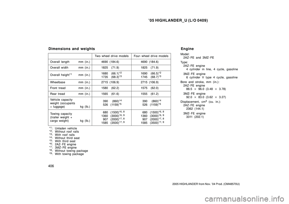
Dimensions and weights406 . . . . . . . . . . . . . . . . . . . . . . . . . . . . . . . . . . . .
Engine406 . . . . . . . . . . . . . . . . . . . . . . . . . . . . . . . . . . . . . . . . . . . . . . . . . . . .
Fuel407 . . . . . . . . . . . . . . . . . . . . . . . . . . . . . . . . . . . . . . . . . . . . . . . . . . . . . . .
Service specifications407 . . . . . . . . . . . . . . . . . . . . . . . . . . . . . . . . . . . . . . .
Tires410 . . . . . . . . . . . . . . . . . . . . . . . . . . . . . . . . . . . . . . . . . . . . . . . . . . . . . .
Fuses410 . . . . . . . . . . . . . . . . . . . . . . . . . . . . . . . . . . . . . . . . . . . . . . . . . . . . .
SECTION 8
Page 102 of 2572

'05 HIGHLANDER_U (L/O 0409)
406
2005 HIGHLANDER from Nov. '04 Prod. (OM48570U)
Model:
2AZ- FE and 3MZ- FE
Type:
2AZ- FE engine
4 cylinder in line, 4 cycle, gasoline
3MZ- FE engine
6 cylinder V type 4 cycle, gasoline
Bore and stroke, mm (in.):
2AZ- FE engine
88.5�96.0 (3.48�3.78)
3MZ- FE engine
92.0�83.0 (3.62�3.27)
Displacement, cm
3 (cu. in.):
2AZ- FE engine
2362 (144.1)
3MZ- FE engine
3311 (202.1)
Dimensions and weights
Overall length mm (in.)
Overall width mm (in.)
Overall height
*
1mm (in.)
Wheelbase mm (in.)
Front tread mm (in.)
Rear tread mm (in.)
Vehicle capacity
weight (occupants
+ luggage) kg (lb.)Two- wheel drive models Four- wheel drive models
4690 (184.6)
4690 (184.6)
1825 (71.9) 1825 (71.9)
1690 (66.5)
*
2
1745 (68.7)*
3
2715 (106.9) 2715 (106.9)
1580 (62.2) 1575 (62.0)
1565 (61.6) 1555 (61.2)
390 (860)
*
4
526 (1159)*
5390 (860)*
4
526 (1159)*
5
*
1
: Unladen vehicle*
2: Without roof rails*
3: With roof rails*
4: Without third seat*
5: With third seat*
6: 2AZ- FE engine*
7: 3MZ- FE engine*
8: Without towing package*
9: With towing package1680 (66.1)
*
2
1735 (68.3)*
3
Towing capacity
(trailer weight +
cargo weight) kg (lb.)680 (1500)*
6, 8
1360 (3000)*
6, 9
907 (2000)*
7, 8
1585 (3500)*
7, 9
680 (1500)*
6, 8
1360 (3000)*
6, 9
907 (2000)*
7, 8
1585 (3500)*
7, 9
Engine
Page 729 of 2572

'05 HIGHLANDER_U (L/O 0409)
287
2005 HIGHLANDER from Nov. '04 Prod. (OM48570U)
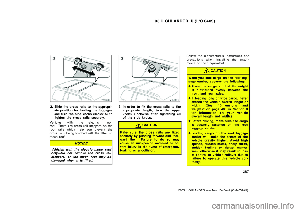
2. Slide the cross rails to the appropri-
ate position for loading the luggages
and turn the side knobs clockwise to
tighten the cross rails securely.
Vehicles with the electric moon
roofÐThere are cross rail stoppers on the
roof rails which help you prevent the
cross rails being touched with the tilted up
moon roof.
NOTICE
Vehicles with the electric moon roof
onlyÐDo not remove the cross rail
stoppers, or the moon roof may be
damaged when it is tilted.
3. In order to fix the cross rails to the
appropriate length, turn the upper
knobs clockwise after tightening all
of the side knobs.
CAUTION
Make sure the cross rails are fixed
securely by pushing forward and rear-
ward them. Failure to do so may
cause an unexpected accident or se-
vere injury in the event of emergency
braking or a collision.
Follow the manufacture's instructions and
precautions when installing the attach-
ments or their equivalent.
CAUTION
When you load cargo on the roof lug-
gage carrier, observe the following:
�Place the cargo so that its weight
is distributed evenly between the
front and rear axles.
�If loading long or wide cargo, never
exceed the vehicle overall length or
width. (See Dimensions and
weightsº on page 406 in Section 8
for information on your vehicle
overall length and width.)
�Before driving, make sure the cargo
is securely fastened on the roof
luggage carrier.
�Loading cargo on the roof luggage
carrier will make the center of the
vehicle gravity higher. Avoid high
speeds, sudden starts, sharp turns,
sudden braking or abrupt maneu-
vers, otherwise it may result in loss
of control or vehicle rollover due to
failure to operate this vehicle cor-
rectly.
Page 755 of 2572

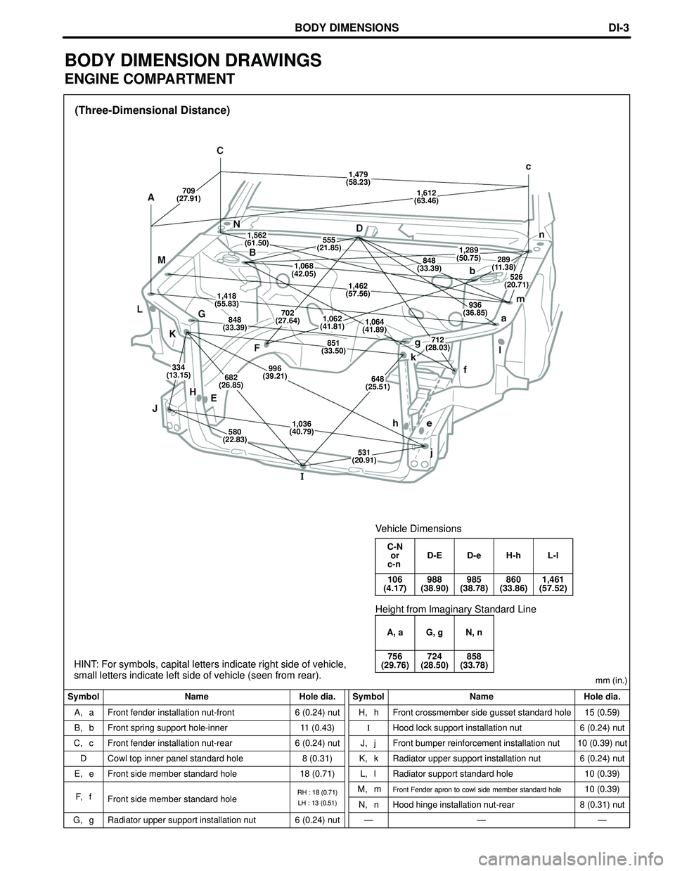
(Three-Dimensional Distance)
Symbol Name Hole dia. Symbol Name Hole dia.mm (in.)
A, a
B, b
C, c
D
E, e
G, gFront fender installation nut-front
Front spring support hole-inner
Front fender installation nut-rear
Cowl top inner panel standard hole
Front side member standard hole
Radiator upper support installation nut6 (0.24) nut
11 (0.43)
6 (0.24) nut
8 (0.31)
18 (0.71)
6 (0.24) nutH, h
I
J, j
K, k
L, l
M, m
N, n
ÐFront crossmember side gusset standard hole
Hood lock support installation nut
Front bumper reinforcement installation nut
Radiator upper support installation nut
Radiator support standard hole
Front Fender apron to cowl side member standard hole
Hood hinge installation nut-rear
Ð15 (0.59)
6 (0.24) nut
10 (0.39) nut
6 (0.24) nut
10 (0.39)
10 (0.39)
8 (0.31) nut
Ð Front side member standard hole F, f
C-N
or D-E D-e H-h L-l
c-n
106 988 985 860 1,461
(4.17) (38.90) (38.78) (33.86) (57.52)
Vehicle Dimensions
RH : 18 (0.71)
LH : 13 (0.51)
A, a G, g N, n
756 724 858
(29.76) (28.50) (33.78)
Height from lmaginary Standard Line
HINT: For symbols, capital letters indicate right side of vehicle,
small letters indicate left side of vehicle (seen from rear).
1,479
(58.23)
709
(27.91)1,612
(63.46)
1,562
(61.50)555
(21.85)1,289
(50.75)848
(33.39)289
(11.38)
526
(20.71)
1,068
(42.05)
1,462
(57.56)1,418
(55.83)936
(36.85)
848
(33.39)702
(27.64)1,062
(41.81)1,064
(41.89)
712
(28.03)851
(33.50)
334
(13.15)682
(26.85)996
(39.21)648
(25.51)
580
(22.83)1,036
(40.79)
531
(20.91)
BODY DIMENSIONSDI-3
BODY DIMENSION DRAWINGS
ENGINE COMPARTMENT
Page 758 of 2572
(Three-Dimensional Distance)
Symbol Name Hole dia. Symbol Name Hole dia.mm (in.)
G, g
I,i
N, n
O, oRocker panel assembly mark
Roof side rail assembly mark
Center body pillar assembly mark
Center body pillar assembly markÐ
Ð
Ð
ÐP, p
Q, q
R, r
S, sRocker panel assembly mark
Roof side rail assembly mark
Quarter panel assembly mark
Quartet panel assembly markÐ
Ð
Ð
Ð
N-n O-o P-p Q-q R-s S-s
1,395 1,502 1,502 1,197 1,254 1,499
(54.92) (59.13) (59.13) (47.13) (49.37) (59.02)
Vehicle Dimensions Left � Right
HINT: For symbols, capital letters indicate right side of vehicle,
small letters indicate left side of vehicle (seen from rear).
G-pI-q N-p N-r N-s O-s P-q R-s
or or or or or or or or
g-P i-Q n-P n-R n-S o-S p-Q r-S
1,928 1,389 1,729 1,564 1,706 1,665 1,747 1,580
(75.91) (54.69) (68.07) (61.57) (67.17) (65.55) (68.78) (62.20)
835
(32.87)
1,120
(44.09)
906
(35.67)1,179
(46.42)
1,271
(50.04)722
(28.43)
BODY DIMENSIONSDI-5
BODY OPENING AREAS (Side View: Rear)
Page 759 of 2572
(Three-Dimensional Distance)
Symbol Name Hole dia. Symbol Name Hole dia.mm (in.)
A, a
B, bBack door hinge installation hole-outer
Back door damper stay installation nut15 (0.59)
6 (0.24) nutD, d
E, e
F, f
G, gQuarter panel standard hole
Deck trim side panel installation hole
Rear spring support hole outer
Center body pillar assembly mark10 (0.39)
7 (0.28)
12.5 (0.492)
Ð Roof side inner front panel / Roof side inner
panel adjoining portion C, c
F-g
C-c or
f-G
1,325 1,812
(52.17) (71.34)
Vehicle Dimensions Left � Right
Ð
1,195
(47.05)
1,227
(48.31)
609
(23.98)
1,330
(52.36)
938
(36.93)1,541
(60.67)
1,251
(49.25)865
(34.06)
1,633
(64.29)1,360
(53.54)
BODY DIMENSIONSDI-6
BODY OPENING AREAS (Rear View)
Page 760 of 2572

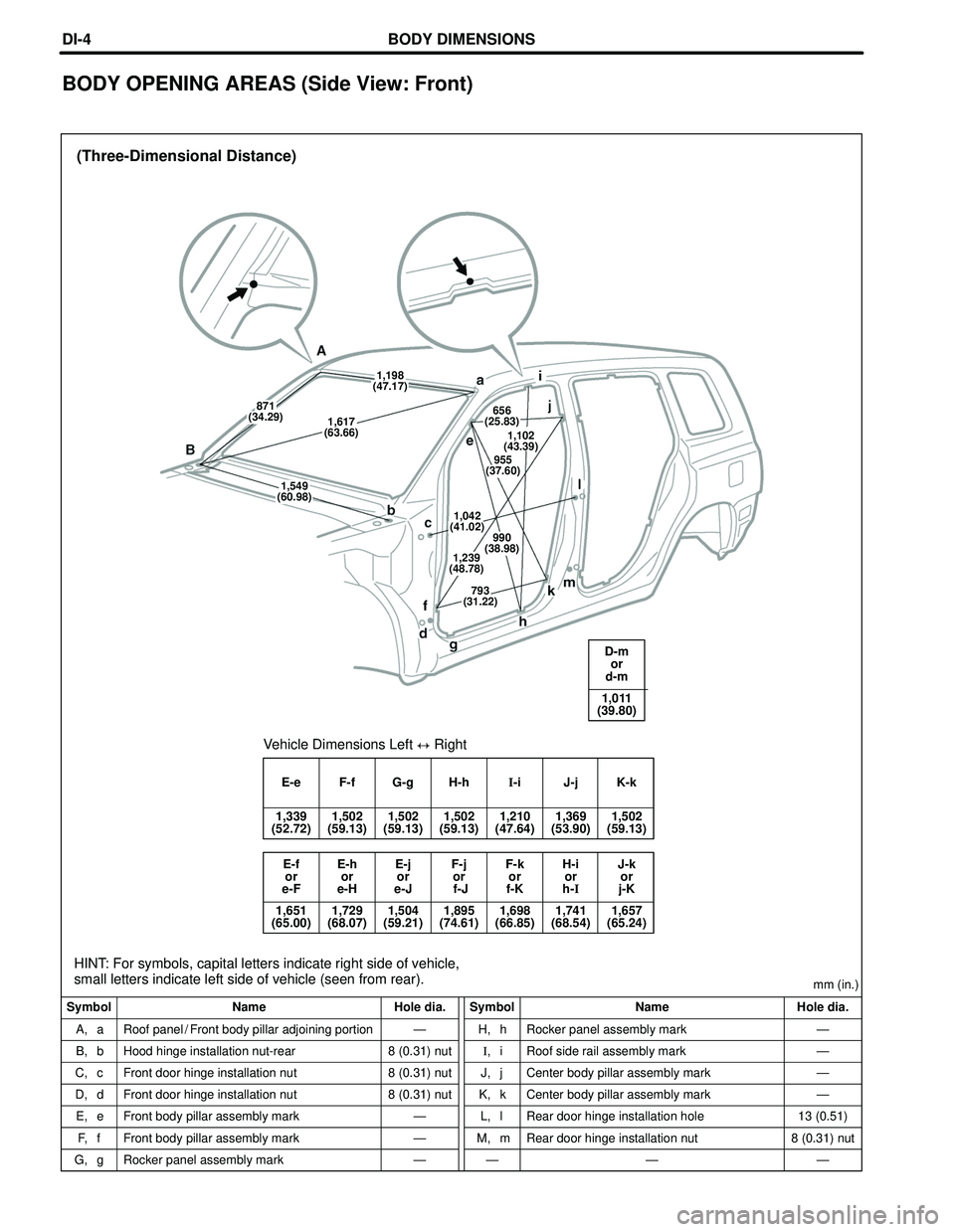
(Three-Dimensional Distance)
Symbol Name Hole dia. Symbol Name Hole dia.mm (in.)
A, a
B, b
C, c
D, d
E, e
F, f
G, gRoof panel / Front body pillar adjoining portion
Hood hinge installation nut-rear
Front door hinge installation nut
Front door hinge installation nut
Front body pillar assembly mark
Front body pillar assembly mark
Rocker panel assembly markÐ
8 (0.31) nut
8 (0.31) nut
8 (0.31) nut
Ð
Ð
ÐH, h
I,i
J, j
K, k
L, l
M, m
ÐRocker panel assembly mark
Roof side rail assembly mark
Center body pillar assembly mark
Center body pillar assembly mark
Rear door hinge installation hole
Rear door hinge installation nut
ÐÐ
Ð
Ð
Ð
13 (0.51)
8 (0.31) nut
Ð
E-e F-f G-g H-hI-i J-j K-k
1,339 1,502 1,502 1,502 1,210 1,369 1,502
(52.72) (59.13) (59.13) (59.13) (47.64) (53.90) (59.13)
Vehicle Dimensions Left � Right
E-f E-h E-j F-j F-k H-i J-k
or or or or or or or
e-F e-H e-J f-J f-K h-Ij-K
1,651 1,729 1,504 1,895 1,698 1,741 1,657
(65.00) (68.07) (59.21) (74.61) (66.85) (68.54) (65.24)
D-m
or
d-m
1,011
(39.80)
HINT: For symbols, capital letters indicate right side of vehicle,
small letters indicate left side of vehicle (seen from rear).
1,198
(47.17)
1,549
(60.98)
871
(34.29)
1,617
(63.66)656
(25.83)
1,102
(43.39)
955
(37.60)
1,042
(41.02)
990
(38.98)
1,239
(48.78)
793
(31.22)
BODY DIMENSIONSDI-4
BODY OPENING AREAS (Side View: Front)
Page 2137 of 2572
BODY DIMENSIONS
(Three-Dimensional Distance)
Symbol Name Hole dia. Symbol Name Hole dia.mm (in.)
A, a
B, b
C, cFront frame standard hole
Front frame standard hole
Front frame standard hole13 (0.51)
13 (0.51)
13 (0.51)D, d
E, e
ÐFront frame standard hole
Lower arm installation hole
Ð13 (0.51)
15 (0.59)
Ð
Imaginary
Standard
Line Front
700
(27.56)
920
(36.22)
945
(37.20)
879
(34.61)
616
(24.25)
738
(29.06)
658
(25.91)
520
(20.47)
486
(19.13)
676
(26.61)
1,029
(40.51)
63
(2.48)57
(2.24)72
(2.83)38
(1.50)55
(2.17)55
(2.17)38
(1.50)72
(2.83)57
(2.24)63
(2.48)
DI-11
FRONT FRAME