Page 2138 of 2572
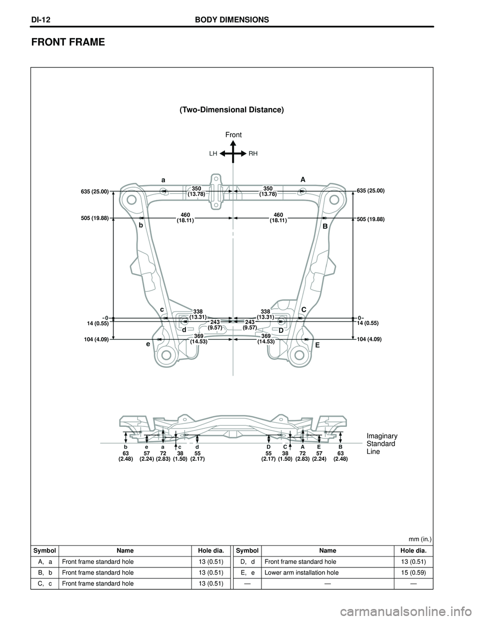
BODY DIMENSIONS
(Two-Dimensional Distance)
Symbol Name Hole dia. Symbol Name Hole dia.mm (in.)
A, a
B, b
C, cFront frame standard hole
Front frame standard hole
Front frame standard hole13 (0.51)
13 (0.51)
13 (0.51)D, d
E, e
ÐFront frame standard hole
Lower arm installation hole
Ð13 (0.51)
15 (0.59)
Ð
Imaginary
Standard
Line Front
350
(13.78) 635 (25.00)
505 (19.88)
14 (0.55)
104 (4.09)104 (4.09) 14 (0.55) 505 (19.88) 635 (25.00)350
(13.78)
460
(18.11)460
(18.11)
338
(13.31)338
(13.31)
369
(14.53)
243
(9.57)243
(9.57)
369
(14.53)
63
(2.48)57
(2.24)72
(2.83)38
(1.50)55
(2.17)55
(2.17)38
(1.50)72
(2.83)57
(2.24)63
(2.48)
DI-12
FRONT FRAME
Page 2142 of 2572
BODY DIMENSIONS
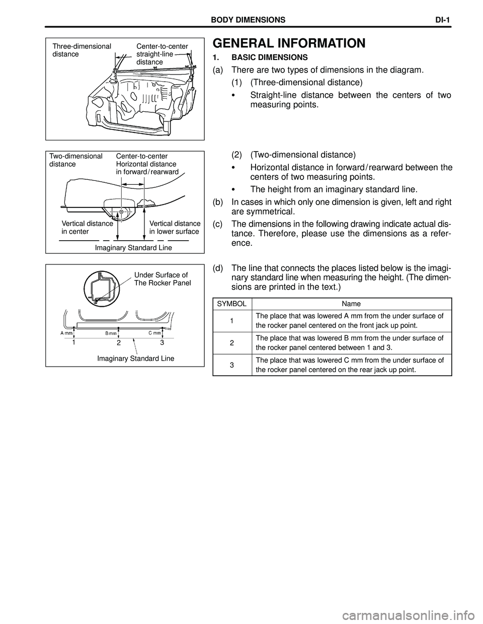
Three-dimensional
distanceCenter-to-center
straight-line
distance
Two-dimensional
distanceCenter-to-center
Horizontal distance
in forward / rearward
Vertical distance
in centerVertical distance
in lower surface
Imaginary Standard Line
Under Surface of
The Rocker Panel
Imaginary Standard Line
DI-1
GENERAL INFORMATION
1. BASIC DIMENSIONS
(a) There are two types of dimensions in the diagram.
(1) (Three-dimensional distance)
�Straight-line distance between the centers of two
measuring points.
(2) (Two-dimensional distance)
�Horizontal distance in forward / rearward between the
centers of two measuring points.
�The height from an imaginary standard line.
(b) In cases in which only one dimension is given, left and right
are symmetrical.
(c) The dimensions in the following drawing indicate actual dis-
tance. Therefore, please use the dimensions as a refer-
ence.
(d) The line that connects the places listed below is the imagi-
nary standard line when measuring the height. (The dimen-
sions are printed in the text.)
SYMBOLName
1The place that was lowered A mm from the under surface of
the rocker panel centered on the front jack up point.
2The place that was lowered B mm from the under surface of
the rocker panel centered between 1 and 3.
3The place that was lowered C mm from the under surface of
the rocker panel centered on the rear jack up point.
Page 2143 of 2572
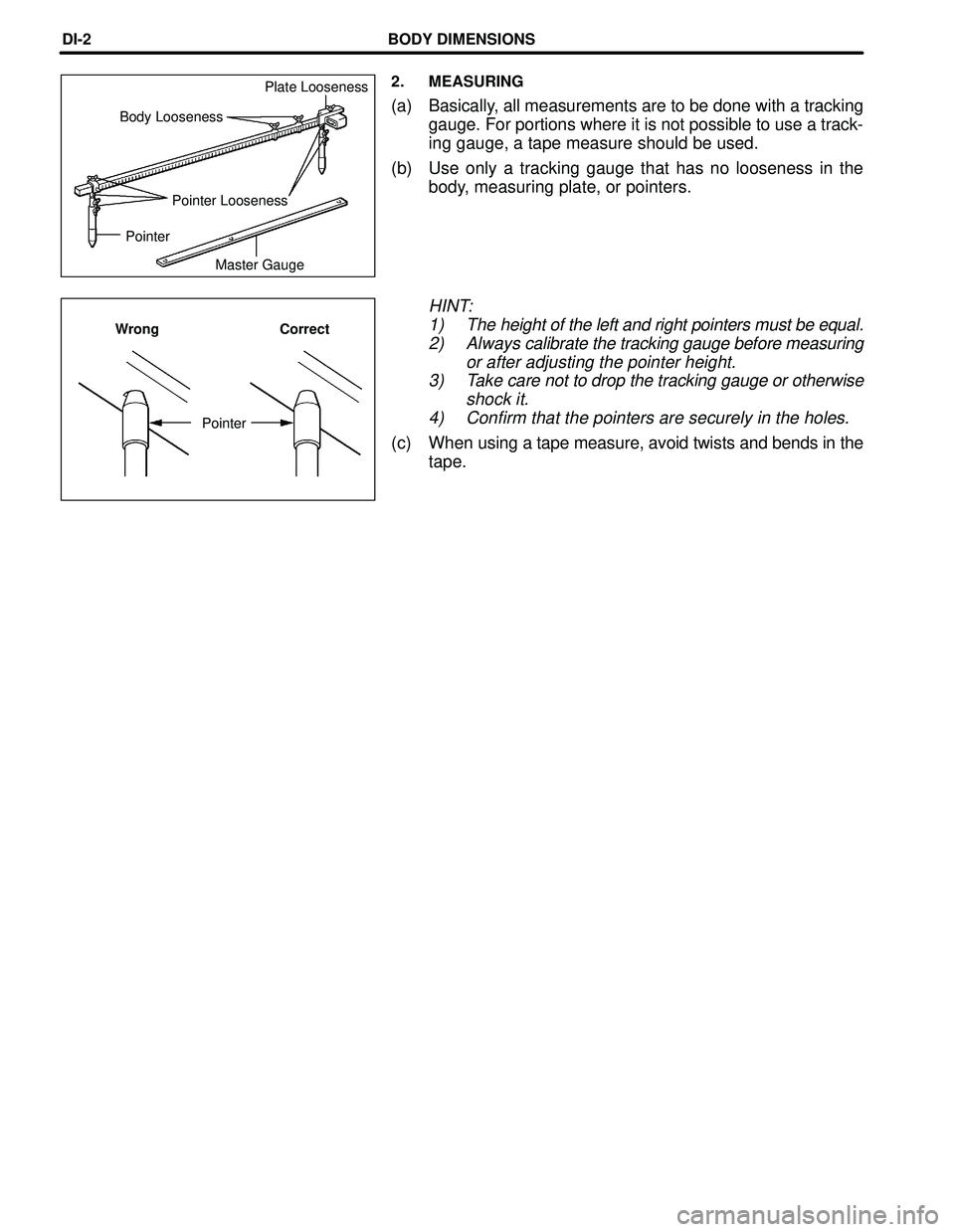
Plate Looseness
Body Looseness
Pointer Looseness
Pointer
Master Gauge
Wrong Correct
Pointer
BODY DIMENSIONSDI-2
2. MEASURING
(a) Basically, all measurements are to be done with a tracking
gauge. For portions where it is not possible to use a track-
ing gauge, a tape measure should be used.
(b) Use only a tracking gauge that has no looseness in the
body, measuring plate, or pointers.
HINT:
1) The height of the left and right pointers must be equal.
2) Always calibrate the tracking gauge before measuring
or after adjusting the pointer height.
3) Take care not to drop the tracking gauge or otherwise
shock it.
4) Confirm that the pointers are securely in the holes.
(c) When using a tape measure, avoid twists and bends in the
tape.
Page 2159 of 2572
INTRODUCTIONIN-15
HANDLING PRECAUTIONS ON RELATED COMPONENTS
1. BRAKE SYSTEM
The brake system is one of the most important safety components. Always follow the directions and
notes given in brake (32) section of the repair manual for the relevant model when handling brake system
parts.
NOTICE: When repairing the brake master cylinder or TRAC system, bleed the air out of the TRAC sys-
tem.
2. DRIVE TRAIN AND CHASSIS
The drive train and chassis are components that can have great effects on the running performance and
vibration resistance of the vehicle. After installing components in the sections listed in the table below,
perform alignments to ensure correct mounting angles and dimensions. Particularly accurate repair of
the body must also be done to ensure correct alignment.
HINT: Correct procedures and special tools are required for alignment. Always follow the directions giv-
en in the repair manual for the relevant model during alignment and section DI of this section.
Component to be alignedSection of repair manual
for relevant model
Front WheelsFront Suspension (26) section
Rear WheelsRear Suspension (27) section
Propeller ShaftPropeller Shaft (30) section
3. COMPONENTS ADJACENT TO THE BODY PANELS
Various types of component parts are mounted directly on or adjacently to the body panels. Strictly ob-
serve the following precautions to prevent damaging these components and the body panels during han-
dling.
�Before repairing the body panels, remove their components or apply protective covers over the com-
ponents.
�Before prying components off using a screwdriver or a scraper, etc., attach protective tape to the tool
tip or blade to prevent damaging the components and the body paint.
�Before removing components from the outer surface of the body, attach protective tape to the body to
ensure no damage to painted areas.
HINT: Apply touch-up paint to any damaged paint surfaces.
�Before drilling or cutting sections, make sure that there are no wires, etc. on the reverse side.
4. ECU (ELECTRONIC CONTROL UNIT)
Many ECUs are mounted in this vehicle.
Take the following precautions during body repair to prevent damage to the ECUs.
�Before starting electric welding operations, disconnect the negative (-) terminal cable from the bat-
tery.
When the negative (-) terminal cable is disconnected from the battery, memory of the clock and audio
systems will be cancelled. So before starting work, make a record of the contents memorized by each
memory system. Then when work is finished, reset the clock and audio systems as before.
When the vehicle has tilt and telescopic steering, power seat and outside rear view mirror, which are
all equipped with memory function, it is not possible to make a record of the memory contents.
So when the operation is finished, it will be necessary to explain this fact to the customer, and request
the customer to adjust the features and reset the memory.
�Do not expose the ECUs to ambient temperatures above 80�C (176�F).
NOTICE: If it is possible the ambient temperature may reach 80�C (176�F) or more, remove the ECUs
from the vehicle before starting work.
�Be careful not to drop the ECUs and not to apply physical shocks to them.
Page 2212 of 2572
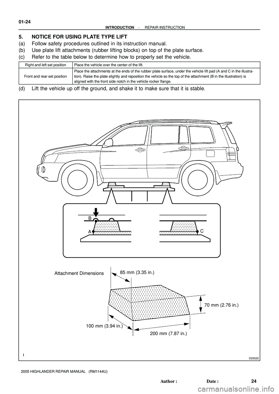
D25522
85 mm (3.35 in.)
70 mm (2.76 in.)
200 mm (7.87 in.) 100 mm (3.94 in.) Attachment DimensionsB
AC 01-24
- INTRODUCTIONREPAIR INSTRUCTION
24 Author�: Date�:
2005 HIGHLANDER REPAIR MANUAL (RM1144U)
5. NOTICE FOR USING PLATE TYPE LIFT
(a) Follow safety procedures outlined in its instruction manual.
(b) Use plate lift attachments (rubber lifting blocks) on top of the plate surface.
(c) Refer to the table below to determine how to properly set the vehicle.
Right and left set positionPlace the vehicle over the center of the lift.
Front and rear set position
Place the attachments at the ends of the rubber plate surface, under the vehicle lift pad (A and C in the illustra-
tion). Raise the plate slightly and reposition the vehicle so the top of the attachment (B in the illustration) is
aligned with the front side notch in the vehicle rocker flange.
(d) Lift the vehicle up off the ground, and shake it to make sure that it is stable.
Page 2427 of 2572
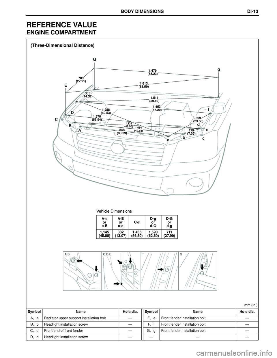
BODY DIMENSIONS
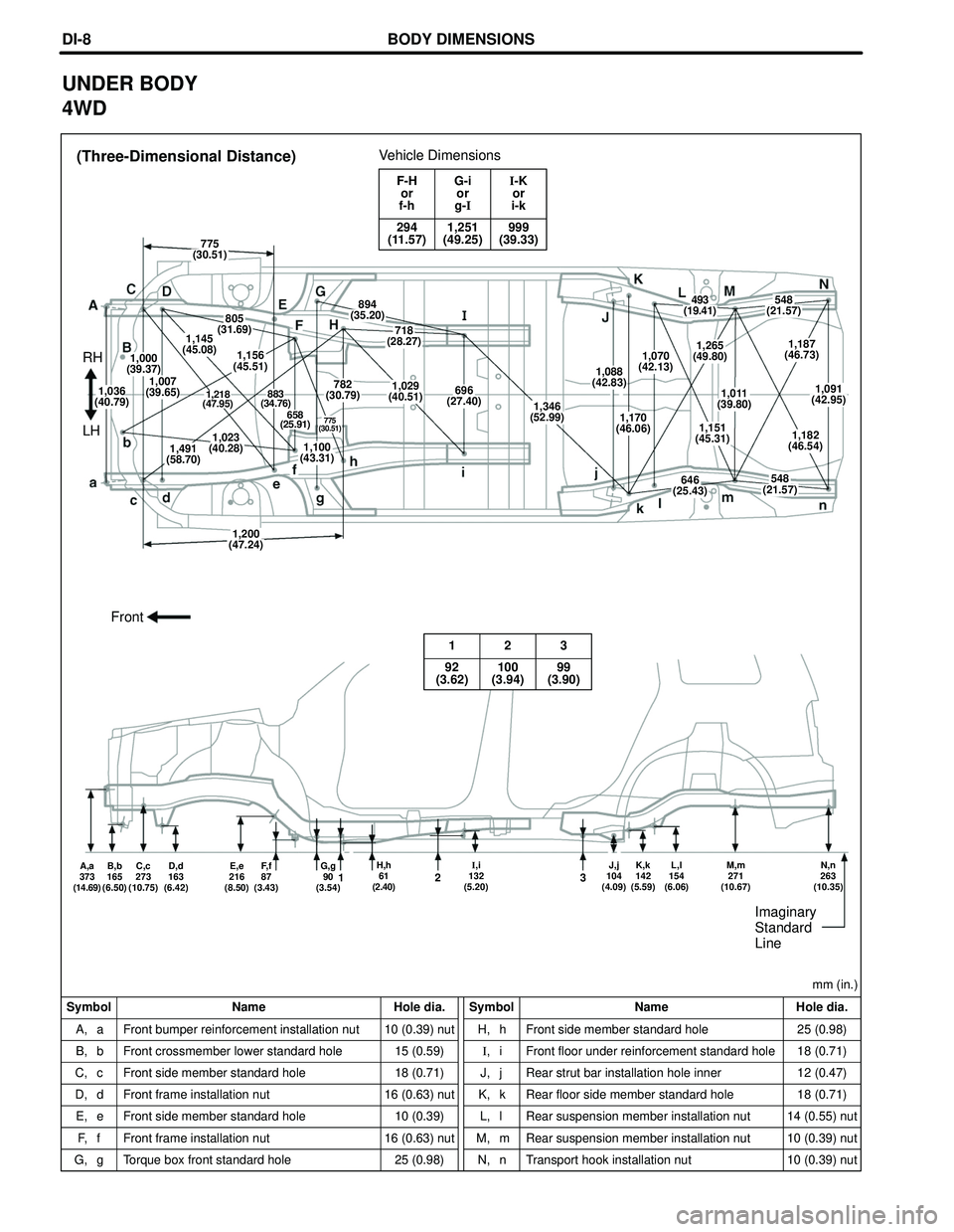
(Three-Dimensional Distance)
Symbol Name Hole dia. Symbol Name Hole dia.mm (in.)
A, a
B, b
C, c
D, dRadiator upper support installation bolt
Headlight installation screw
Front end of front fender
Headlight installation screwÐ
Ð
Ð
ÐE, e
F, f
G, g
ÐFront fender installation bolt
Front fender installation bolt
Front fender installation bolt
ÐÐ
Ð
Ð
Ð
A-e A-E D-g D-G
or or C-c or or
a-E a-e d-G d-g
1,145 332 1,435 1,590 711
(45.08) (13.07) (56.50) (62.60) (27.99)
Vehicle Dimensions
1,479
(58.23)
709
(27.91)
1,613
(63.50)
365
(14.37)
1,511
(59.49)
1,258
(49.53)
599
(23.58)1,370
(53.94)
1,232
(48.50)1,084
(42.68)848
(33.39)179
(7.05)
1,453
(57.20)
DI-13
REFERENCE VALUE
ENGINE COMPARTMENT
Page 2428 of 2572
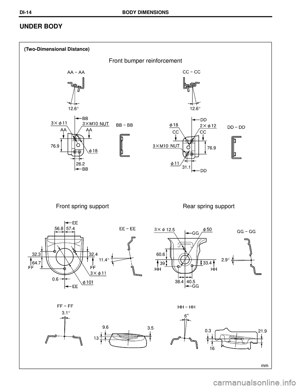
(Two-Dimensional Distance)
Front bumper reinforcement
Front spring support Rear spring support
NUT
NUT
26.2 76.9
76.9
31.1 12.6�
57.4 56.812.6�
32.3
64.7
0.632.412.5
60.6
38.4 40.533.42.9� 11.4�
9.6 3.1�
3.5
0.3
21.9
mm
BODY DIMENSIONSDI-14
UNDER BODY
Page 2496 of 2572
Front
123
92 100 99
(3.62) (3.94) (3.90)
F-H G-iI-K
or or or
f-h g-Ii-k
294 1,251 999
(11.57) (49.25) (39.33)
Vehicle Dimensions(Three-Dimensional Distance)
Symbol Name Hole dia. Symbol Name Hole dia.mm (in.)
A, a
B, b
C, c
D, d
E, e
F, f
G, gFront bumper reinforcement installation nut
Front crossmember lower standard hole
Front side member standard hole
Front frame installation nut
Front side member standard hole
Front frame installation nut
Torque box front standard hole10 (0.39) nut
15 (0.59)
18 (0.71)
16 (0.63) nut
10 (0.39)
16 (0.63) nut
25 (0.98)H, h
I,i
J, j
K, k
L, l
M, m
N, nFront side member standard hole
Front floor under reinforcement standard hole
Rear strut bar installation hole inner
Rear floor side member standard hole
Rear suspension member installation nut
Rear suspension member installation nut
Transport hook installation nut25 (0.98)
18 (0.71)
12 (0.47)
18 (0.71)
14 (0.55) nut
10 (0.39) nut
10 (0.39) nut
Imaginary
Standard
Line
775
(30.51)
805
(31.69)
1,036
(40.79)
1,000
(39.37)
1,007
(39.65)
1,145
(45.08)
1,156
(45.51)
1,200
(47.24)
1,491
(58.70)1,023
(40.28)
1,218
(47.95)
1,100
(43.31)
883
(34.76)
658
(25.91)775
(30.51)
782
(30.79)
894
(35.20)
718
(28.27)
1,029
(40.51)696
(27.40)
1,346
(52.99)
1,088
(42.83)
1,070
(42.13)
1,170
(46.06)1,151
(45.31)
493
(19.41)548
(21.57)
646
(25.43)
1,091
(42.95)
1,182
(46.54)
548
(21.57)
1,265
(49.80)
1,011
(39.80)
1,187
(46.73)RH
LH
A,a
373
(14.69)B,b
165
(6.50)C,c
273
(10.75)D,d
163
(6.42)E,e
216
(8.50)F, f
87
(3.43)G,g
90
(3.54)1H,h
61
(2.40)2I,i
132
(5.20)3J,j
104
(4.09)K,k
142
(5.59)L,l
154
(6.06)M,m
271
(10.67)N,n
263
(10.35)
BODY DIMENSIONSDI-8
UNDER BODY
4WD