Page 56 of 2572

'05 HIGHLANDER_U (L/O 0409)
326
2005 HIGHLANDER from Nov. '04 Prod. (OM48570U)
TRAILER LIGHTS
�Your vehicle is equipped with a wire
harness stored in the rear end under
body. Some models are fitted with a
socket for trailer lights under the rear
bumper. Use either of them to connect
and operate the trailer lights. However,
the trailer lights must comply with fed-
eral, state/provincial and local regula-
tions. See your local recreational ve-
hicle dealer or rental agency for the
correct type of wiring and relays for
your trailer. Check for correct operation
of the turn signals and stop lights each
time you hitch up. Direct splicing may
damage your vehicle's electrical system
and cause a malfunction of your lights.BREAK- IN SCHEDULE
�Toyota recommends that you do not
tow a trailer with a new vehicle or a
vehicle with any new power train com-
ponent (engine, transmission, differen-
tial, wheel bearings, etc.) for the first
800 km (500 miles) of driving.
MAINTENANCE
�If you tow a trailer, your vehicle will
require more frequent maintenance due
to the additional load. For this informa-
tion, please refer to the scheduled
maintenance information in the Sched-
uled Maintenance Guideº or Owner 's
Manual Supplementº.
�Retighten all fixing bolts of the towing
ball and bracket after approximately
1000 km (600 miles) of trailer driving.PRE- TOWING SAFETY CHECK
�Check that your vehicle remains level
when a loaded or unloaded trailer is
hitched. Do not drive if the vehicle has
an abnormal nose- up or nose- down
condition, and check for improper
tongue load, overload, worn suspension
or other possible causes.
�Make sure the trailer cargo is securely
loaded so that it cannot shift.
�Check that your rear view mirrors con-
form to any applicable federal, state/
provincial or local regulations. If not,
install the rear view mirrors required
for towing purposes.
TRAILER TOWING TIPS
When towing a trailer, your vehicle will
handle differently than when not tow-
ing. The three main causes of vehicle-
trailer accidents are driver error, exces-
sive speed and improper trailer loading.
Keep these in mind when towing:
�Before starting out, check operation of
the lights and all vehicle- trailer connec-
tions. After driving a short distance,
stop and recheck the lights and con-
nections. Before actually towing a trail-
er, practice turning, stopping and back-
ing with a trailer in an area away from
traffic until you learn the feel.
Page 125 of 2572
2005 HIGHLANDER (EWD592U)
62
Power Source
B1
1A 1C6
5
13
2 15A SEAT HTR
20A P FR DOOR40A AM1
20A P RR DOOR
25A D FR DOOR
20A FR DEF
20A FR FOG
7. 5A OBD
20A STOP
20A S/ROOF
30A POWER
WW
2645
11
397. 5A PANEL
10A TAIL
TAI LL I GHT Rela y
W
W
G WY BB- R
140A ALT
30A RDI
30A CDS
30A RR DEF
Battery
FAN NO. 1 Relay
FAN NO. 3 Relay
RR DEF Relay
ABS CUT Relay2
12
15A PWR OUTLET1
212
2G
25A A/F20A D RR DOOR
30A ABS1
50A ABS2
30A AM2
FL MAI N
3. 0W7
B- Y 50A HTR
HEATER Relay
810
BIC1 1Y
L- Y
Y W
Skid Control ECU with Actuator
F 7
212
2B- R
15A RR HTR
12
2R
10A ETCS
212
2V
7. 5A CRT E1 5
E1 5W
W
W
W
Fusible Link Block
Page 126 of 2572
2005 HIGHLANDER (EWD592U)
63
1
2I
3 2
4 1
2G133 I15
B
HEAD LAMP Relay
20A EFI NO. 110A HORN10A H- LP LH UPR 10A H- LP RH UPR
40A MAIN D. C. C
7. 5A ALT- S
2 125A DOOR LOCK
15A HAZARD7. 5A ECU- B
15A SECURITY25A RAD NO. 1
10A DOME 2
73
4
6 AM2 AM1ACC
IG1
IG2
ST21C2
10A IGN
15A IG215A RR WIP25A WIPER 10A ECU- IG 20A WASHER7. 5A IG1
1C715A CIG
7. 5A RAD NO. 2 L
L
G
GR
1C1
1C4
R- B
W W
2 1
7. 5A DRL
2 2 1
15A H- LP LH LWR 222 1
15A H- LP RH LWR1
32
53
3 3
DRL NO. 2 Relay 3 2G4
E10R- B
R- B R- B
BL- R
20A TOWING Y
1G1
212
2L
E10B
B
(
*2)(
*1)
(
*1)(
*1) * 1 : w/ Daytime Running Light
* 2 : w/o Daytime Running Light
7. 5A STARTER10A HEATER
(
*1)(
*1) (
*1)(
*1)
2 3
1 5
2D3
EFI RelayY
222 1
10A EFI NO. 2L- W
B- W R- WR- Y 1 ST1
IC1 3 B
B- Y
20A POWER OUTLET28
B- W
STARTER RelayIgnition SW
Page 127 of 2572

2005 HIGHLANDER (EWD592U)
64
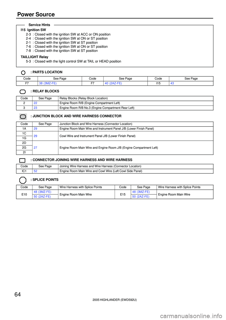
Power Source
I15 Ignition SW
2-3 : Closed with the ignition SW at ACC or ON position
2-4 : Closed with the ignition SW at ON or ST position
2-1 : Closed with the ignition SW at ST position
7-6 : Closed with the ignition SW at ON or ST position
7-8 : Closed with the ignition SW at ST position
TAILLIGHT Relay
5-3 : Closed with the light control SW at TAIL or HEAD position
: PARTS LOCATION
CodeSee PageCodeSee PageCodeSee Page
F738 (3MZ-FE)F740 (2AZ-FE)I1543
: RELAY BLOCKS
CodeSee PageRelay Blocks (Relay Block Location)
222Engine Room R/B (Engine Compartment Left)
323Engine Room R/B No.3 (Engine Compartment Rear Left)
������ ���: JUNCTION BLOCK AND WIRE HARNESS CONNECTOR
CodeSee PageJunction Block and Wire Harness (Connector Location)
1A29Engine Room Main Wire and Instrument Panel J/B (Lower Finish Panel)
1C29Cowl Wire and Instrument Panel J/B (Lower Finish Panel)1G29Cowl Wire and Instrument Panel J/B (Lower Finish Panel)
2D
2G27Engine Room Main Wire and Engine Room J/B (Engine Compartment Left)
2I
gg(g)
: CONNECTOR JOINING WIRE HARNESS AND WIRE HARNESS
CodeSee PageJoining Wire Harness and Wire Harness (Connector Location)
IC152Engine Room Main Wire and Cowl Wire (Left Cowl Side Panel)
: SPLICE POINTS
CodeSee PageWire Harness with Splice PointsCodeSee PageWire Harness with Splice Points
E1048 (3MZ-FE)Engine Room Main WireE1548 (3MZ-FE)Engine Room Main WireE1050 (2AZ-FE)Engine Room Main WireE1550 (2AZ-FE)Engine Room Main Wire
Service Hints
Page 155 of 2572
2005 HIGHLANDER (EWD592U)
66
Starting and Ignition
M1
Battery
A 1
B1
W
BR
R
W- B
B 76
8 AM2 IG2
ST2
I15
IC1 1
30A AM2
10
1
F 7Y L- Y
EB1 4IC1 2
22 22
7. 5A
STARTER
2 2
EB23 B- W
STARTER
Relay
2
P
N
4
W- BB- RW- R B- WL
1
B- R 1G 11C 1
15A
IG2 1F 6
1C 4 GR
BN 1B- W
B- R
B
NSW
E 7 FL MAI N
3. 0W51
32
STAIC31
O
E 7 2
1 ACC
IG1
ST1
3IC1
EB2 4
5E 7
P 1
EH A
J 2
1A 1
140A ALT
2 1
40A AM1
21C 6
W- BW- BB- YW B
B
L- W
B
B B
AM1
EC : * 1
EF : * 217 16 S 1(
A)
, S 2(
B)
Engine Control Module
Fusible Link Block
Ignition SW
Junction
Connector
Noise Filter
(
Ignition System) Park/Neutral
Position SW
Starter
Page 157 of 2572

2005 HIGHLANDER (EWD592U)
68
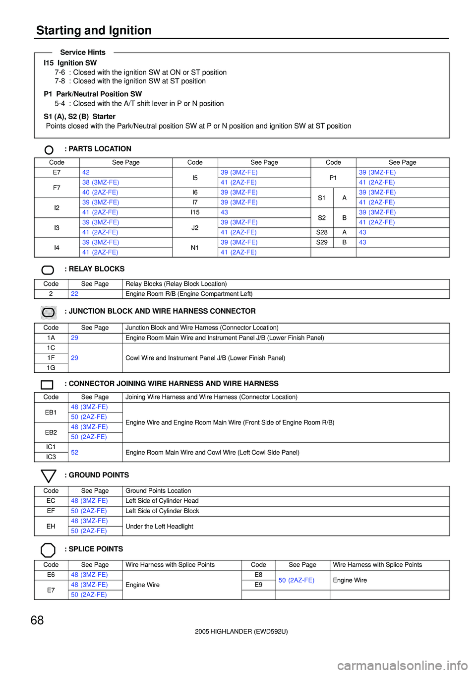
Starting and Ignition
I15 Ignition SW
7-6 : Closed with the ignition SW at ON or ST position
7-8 : Closed with the ignition SW at ST position
P1
Park/Neutral Position SW
5-4 : Closed with the A/T shift lever in P or N position
S1 (A), S2 (B) Starter
Points closed with the Park/Neutral position SW at P or N position and ignition SW at ST position
: PARTS LOCATION
CodeSee PageCodeSee PageCodeSee Page
E742I539 (3MZ-FE)P139 (3MZ-FE)
F738 (3MZ-FE)I541 (2AZ-FE)P141 (2AZ-FE)F740 (2AZ-FE)I639 (3MZ-FE)S1A39 (3MZ-FE)
I239 (3MZ-FE)I739 (3MZ-FE)S1A41 (2AZ-FE)I241 (2AZ-FE)I1543S2B39 (3MZ-FE)
I339 (3MZ-FE)J239 (3MZ-FE)S2B41 (2AZ-FE)I341 (2AZ-FE)J241 (2AZ-FE)S28A43
I439 (3MZ-FE)N139 (3MZ-FE)S29B43I441 (2AZ-FE)N141 (2AZ-FE)
: RELAY BLOCKS
CodeSee PageRelay Blocks (Relay Block Location)
222Engine Room R/B (Engine Compartment Left)
������ ���: JUNCTION BLOCK AND WIRE HARNESS CONNECTOR
CodeSee PageJunction Block and Wire Harness (Connector Location)
1A29Engine Room Main Wire and Instrument Panel J/B (Lower Finish Panel)
1C
1F29Cowl Wire and Instrument Panel J/B (Lower Finish Panel)
1G
()
: CONNECTOR JOINING WIRE HARNESS AND WIRE HARNESS
CodeSee PageJoining Wire Harness and Wire Harness (Connector Location)
EB148 (3MZ-FE)EB150 (2AZ-FE)Engine Wire and Engine Room Main Wire (Front Side of Engine Room R/B)
EB248 (3MZ-FE)Engine Wire and Engine Room Main Wire (Front Side of Engine Room R/B)
EB250 (2AZ-FE)
IC152Engine Room Main Wire and Cowl Wire (Left Cowl Side Panel)IC352Engine Room Main Wire and Cowl Wire (Left Cowl Side Panel)
: GROUND POINTS
CodeSee PageGround Points Location
EC48 (3MZ-FE)Left Side of Cylinder Head
EF50 (2AZ-FE)Left Side of Cylinder Block
EH48 (3MZ-FE)Under the Left HeadlightEH50 (2AZ-FE)Under the Left Headlight
: SPLICE POINTS
CodeSee PageWire Harness with Splice PointsCodeSee PageWire Harness with Splice Points
E648 (3MZ-FE)E850 (2AZ FE)Engine Wire
E748 (3MZ-FE)Engine WireE950 (2AZ-FE)Engine Wire
E750 (2AZ-FE)
g
Service Hints
Page 243 of 2572
2005 HIGHLANDER (EWD592U)
74
Engine Control for 3MZ-FE
E 6
10A IGN
11
11 IC3 6
1 2
1 2
1 2
1 2
1 2
1 2
5 4 23 15
BCG
B- W
W
B
Y
L
BR L W- BR
R R R R R R
G B- WWB YL
YCIRCUIT OPENING
Relay I 8
I 9
I10
I11
I12
I13
W- B 1 5
2 32 25A
A/F
2 2
P
A/F Relay
Y P- L
G
P- L
2
B W- BW P4M 4
4E 1
15A IG2
1G 9
LG
1G 6
M EB1 5
R2
W- B R- W
2
W
P
B
E E
J 3
P
R- W E
P
4F 1
W
IA2 8 Fr om Power Source System (
See Page 62)
Injector No. 1
Injector No. 2
Injector No. 3
Injector No. 4
Injector No. 5
Injector No. 6
Ju nctio n
Connector
Fuel Pump F12
Page 244 of 2572
2005 HIGHLANDER (EWD592U)
75
7
2B 2G 5
2F 42B8 23 15
D 3E5E4 A 1A3
EH20A
EFI NO. 1
B- R G
B- W
W
B
Y
L
G
3
BRW W- B
B- W
W W- B
EFI Relay
+B BATT
#60 #50 #40 2A 7
W- B
MREL
A 8
P Y P- L
B 2DB- W
A 2B
P- L
5
W- BA 9IGSW
Y
A 10FC
W
IC2 2
B W
IK3 13
B
EB1 1
Y
I 7
B- R B- W J 2
IK2 11
B- W
A 2
+B2
W
E14 10A
EFI
NO. 22
22B4
W
W
2 12 1
ACM
B- W V 5
Y- G
C 6
B
7 EB2 P
Y
L BR- W
B- R
P
IK2 10
W
B- R
B- R
B- W
B
BRBR
R- WP
From Power Source System (
See Page 62)
E 5(
A)
, E 6(
B)
, E 7(
E)
, E 8(
D)
, E 9(
C)
Engine Control Module
Junction
Connector
VSV (
ACM)