Page 2443 of 2572
2005 HIGHLANDER (EWD592U)
34
F RELAY LOCATIONS
[Engine Room J/B Inner Circuit]
Page 2445 of 2572
2005 HIGHLANDER (EWD592U)
36
F RELAY LOCATIONS
[Center J/B Inner Circuit]
Page 2475 of 2572

051ZJ-16
A53766
E7E8E9E6E5
05-32
- DIAGNOSTICSSFI SYSTEM (2AZ-FE)
222 Author�: Date�:
2005 HIGHLANDER REPAIR MANUAL (RM1144U)
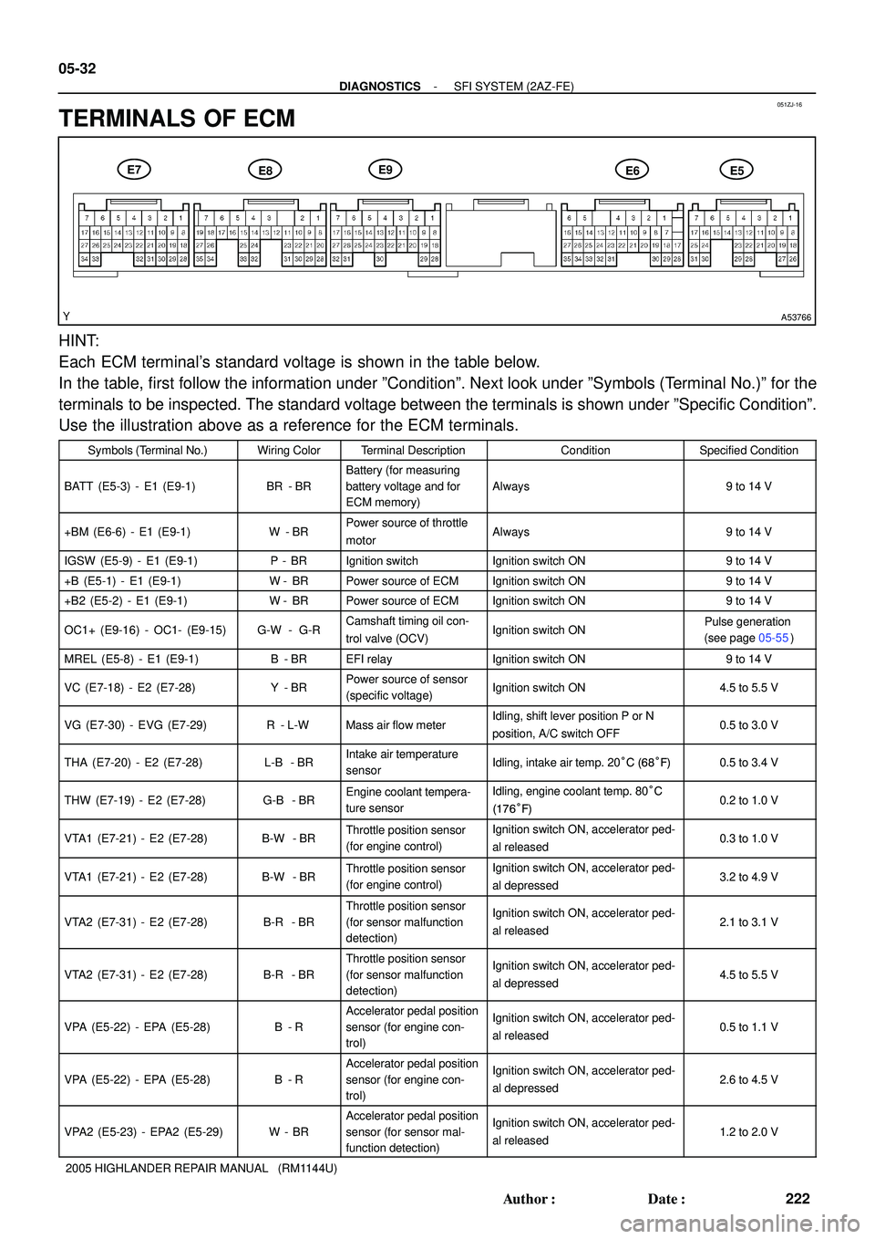
TERMINALS OF ECM
HINT:
Each ECM terminal's standard voltage is shown in the table below.
In the table, first follow the information under ºConditionº. Next look under ºSymbols (Terminal No.)º for the
terminals to be inspected. The standard voltage between the terminals is shown under ºSpecific Conditionº.
Use the illustration above as a reference for the ECM terminals.
Symbols (Terminal No.)Wiring ColorTerminal DescriptionConditionSpecified Condition
BATT (E5-3) - E1 (E9-1)BR - BR
Battery (for measuring
battery voltage and for
ECM memory)
Always9 to 14 V
+BM (E6-6) - E1 (E9-1)W - BRPower source of throttle
motorAlways9 to 14 V
IGSW (E5-9) - E1 (E9-1)P - BRIgnition switchIgnition switch ON9 to 14 V
+B (E5-1) - E1 (E9-1)W- BRPower source of ECMIgnition switch ON9 to 14 V
+B2 (E5-2) - E1 (E9-1)W- BRPower source of ECMIgnition switch ON9 to 14 V
OC1+ (E9-16) - OC1- (E9-15)G-W - G-RCamshaft timing oil con-
trol valve (OCV)Ignition switch ONPulse generation
(see page 05-55)
MREL (E5-8) - E1 (E9-1)B - BREFI relayIgnition switch ON9 to 14 V
VC (E7-18) - E2 (E7-28)Y - BRPower source of sensor
(specific voltage)Ignition switch ON4.5 to 5.5 V
VG (E7-30) - EVG (E7-29)R - L-WMass air flow meterIdling, shift lever position P or N
position, A/C switch OFF0.5 to 3.0 V
THA (E7-20) - E2 (E7-28)L-B - BRIntake air temperature
sensorIdling, intake air temp. 20°C (68°F)0.5 to 3.4 V
THW (E7-19) - E2 (E7-28)G-B - BREngine coolant tempera-
ture sensorIdling, engine coolant temp. 80°C
(176°F)0.2 to 1.0 V
VTA1 (E7-21) - E2 (E7-28)B-W - BRThrottle position sensor
(for engine control)Ignition switch ON, accelerator ped-
al released0.3 to 1.0 V
VTA1 (E7-21) - E2 (E7-28)B-W - BRThrottle position sensor
(for engine control)Ignition switch ON, accelerator ped-
al depressed3.2 to 4.9 V
VTA2 (E7-31) - E2 (E7-28)B-R - BR
Throttle position sensor
(for sensor malfunction
detection)Ignition switch ON, accelerator ped-
al released2.1 to 3.1 V
VTA2 (E7-31) - E2 (E7-28)B-R - BR
Throttle position sensor
(for sensor malfunction
detection)Ignition switch ON, accelerator ped-
al depressed4.5 to 5.5 V
VPA (E5-22) - EPA (E5-28)B - R
Accelerator pedal position
sensor (for engine con-
trol)Ignition switch ON, accelerator ped-
al released0.5 to 1.1 V
VPA (E5-22) - EPA (E5-28)B - R
Accelerator pedal position
sensor (for engine con-
trol)Ignition switch ON, accelerator ped-
al depressed2.6 to 4.5 V
VPA2 (E5-23) - EPA2 (E5-29)W - BR
Accelerator pedal position
sensor (for sensor mal-
function detection)Ignition switch ON, accelerator ped-
al released1.2 to 2.0 V
Page 2478 of 2572

05CD1-12
F45080
S27
05-784
- DIAGNOSTICSABS WITH EBD & BA & TRAC & VSC SYSTEM
974 Author�: Date�:
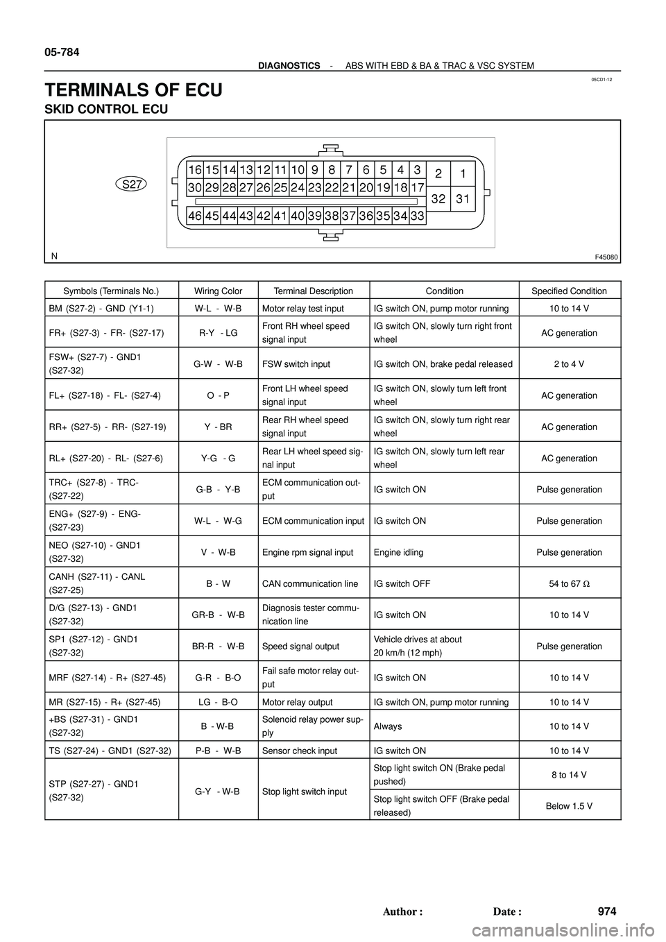
TERMINALS OF ECU
SKID CONTROL ECU
Symbols (Terminals No.)Wiring ColorTerminal DescriptionConditionSpecified Condition
BM (S27-2) - GND (Y1-1)W-L - W-BMotor relay test inputIG switch ON, pump motor running10 to 14 V
FR+ (S27-3) - FR- (S27-17)R-Y - LGFront RH wheel speed
signal inputIG switch ON, slowly turn right front
wheelAC generation
FSW+ (S27-7) - GND1
(S27-32)G-W - W-BFSW switch inputIG switch ON, brake pedal released2 to 4 V
FL+ (S27-18) - FL- (S27-4)O - PFront LH wheel speed
signal inputIG switch ON, slowly turn left front
wheelAC generation
RR+ (S27-5) - RR- (S27-19)Y - BRRear RH wheel speed
signal inputIG switch ON, slowly turn right rear
wheelAC generation
RL+ (S27-20) - RL- (S27-6)Y-G - GRear LH wheel speed sig-
nal inputIG switch ON, slowly turn left rear
wheelAC generation
TRC+ (S27-8) - TRC-
(S27-22)G-B - Y-BECM communication out-
putIG switch ONPulse generation
ENG+ (S27-9) - ENG-
(S27-23)W-L - W-GECM communication inputIG switch ONPulse generation
NEO (S27-10) - GND1
(S27-32)V - W-BEngine rpm signal inputEngine idlingPulse generation
CANH (S27-11) - CANL
(S27-25)B - WCAN communication lineIG switch OFF54 to 67 W
D/G (S27-13) - GND1
(S27-32)GR-B - W-BDiagnosis tester commu-
nication lineIG switch ON10 to 14 V
SP1 (S27-12) - GND1
(S27-32)BR-R - W-BSpeed signal outputVehicle drives at about
20 km/h (12 mph)Pulse generation
MRF (S27-14) - R+ (S27-45)G-R - B-OFail safe motor relay out-
putIG switch ON10 to 14 V
MR (S27-15) - R+ (S27-45)LG - B-OMotor relay outputIG switch ON, pump motor running10 to 14 V
+BS (S27-31) - GND1
(S27-32)B - W-BSolenoid relay power sup-
plyAlways10 to 14 V
TS (S27-24) - GND1 (S27-32)P-B - W-BSensor check inputIG switch ON10 to 14 V
STP (S27-27) - GND1GY WBSt li ht it h i t
Stop light switch ON (Brake pedal
pushed)8 to 14 VSTP (S27 27) GND1
(S27-32)G-Y - W-BStop light switch inputStop light switch OFF (Brake pedal
released)Below 1.5 V
Page 2479 of 2572

- DIAGNOSTICSABS WITH EBD & BA & TRAC & VSC SYSTEM
05-785
975 Author�: Date�:
PKB (S27-28) - GND1RW WBParking brake switch in-
IG switch ON, parking brake switch
ONBelow 1.5 VPKB (S27 28) GND1
(S27-32)R-W - W-BParking brake switch in
putIG switch ON, parking brake switch
OFF10 to 14 V
WA (S27-29) - GND1RL WBABS ilihttt
IG switch ON, ABS warning light
ON6 to 11 VWA (S27 29) GND1
(S27-32)R-L - W-BABS warning light outputIG switch ON, ABS warning light
OFFBelow 2.0 V
IG switch ON, VSC buzzer soundsBelow 1.0 e 10 to 14 V
BZ (S27-30) - GND1 (S27-32)BR-W - W-BBuzzer outputIG switch ON, VSC buzzer does not
sound10 to 14 V
VSCW (S27-36) - GND1
(S27-32)L-Y - W-BVSC warning light outputIG switch ON, VSC warning light
ONBelow 2.0 V
CSW* (S27-43) - GND1
(S27-32)L-R - W-BTRAC OFF switch inputTRAC OFF switch OFF10 to 14 V
BRL (S27-44) - GND1LG B W BBk ilihttt
IG switch ON, BRAKE warning light
ON6 to 11 VBRL (S27 44) GND1
(S27-32)LG-B - W-BBrake warning light outputIG switch ON, BRAKE warning light
OFFBelow 2.0 V
R+ (S27-45) - GND1 (S27-32)B-O - W-BPower supply for motor
relayIG switch ON10 to 14 V
IG1 (S27-46) - GND1
(S27-32)B-R - W-BIG1 power supplyIG switch ON10 to 14 V
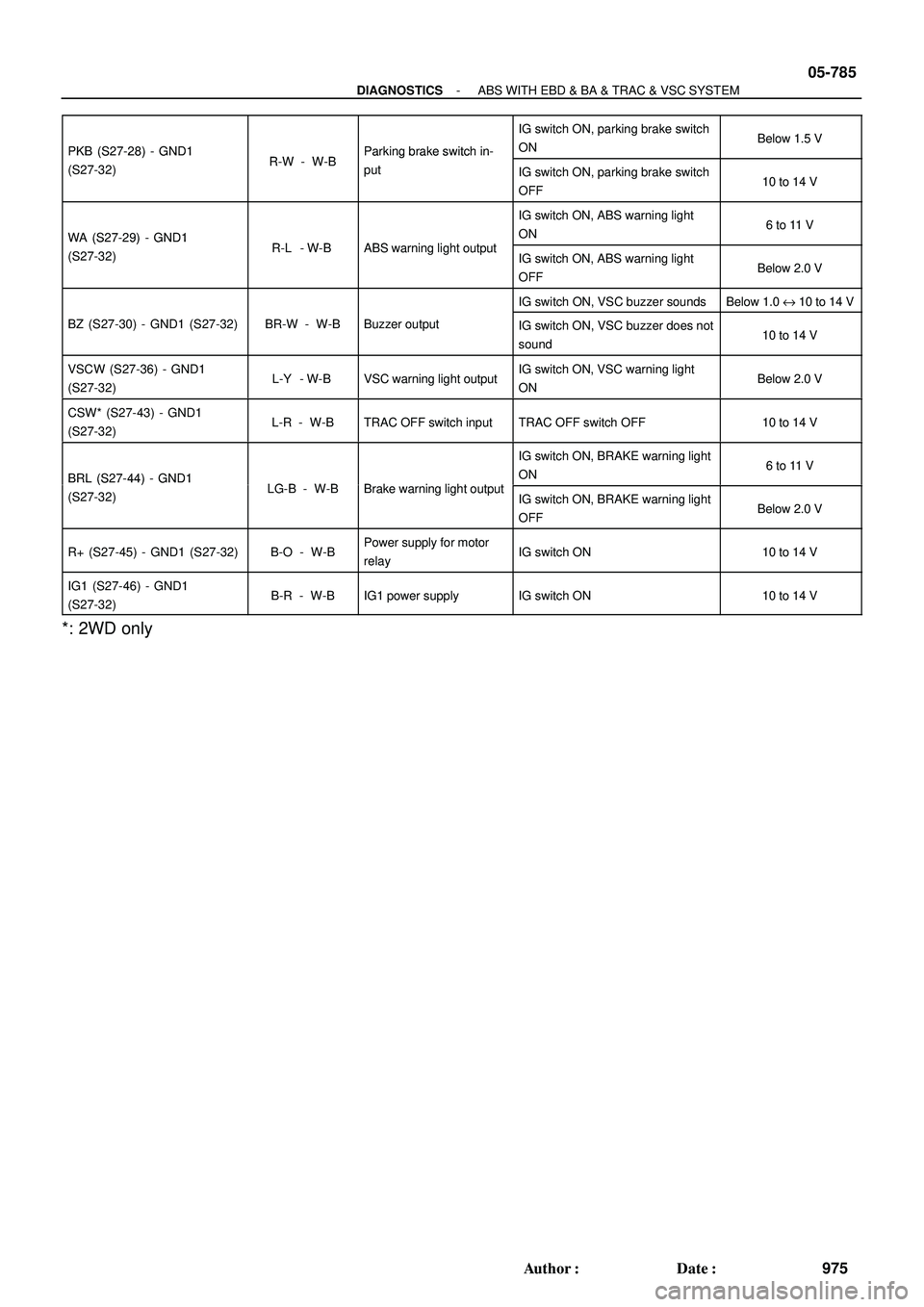
*: 2WD only
Page 2488 of 2572
![TOYOTA HIGHLANDER 2001 Service Repair Manual To Ignition SW
IG Terminal
Fuse
Voltmeter SW 1
Relay
SW 2Solenoid[A]
[B]
[C]
Ohmmeter
SW
Ohmmeter
Diode
Digital Type Analog Type
2005 HIGHLANDER (EWD592U)
12
C TROUBLESHOOTING
VOLTAGE CHECK
(a)Establ TOYOTA HIGHLANDER 2001 Service Repair Manual To Ignition SW
IG Terminal
Fuse
Voltmeter SW 1
Relay
SW 2Solenoid[A]
[B]
[C]
Ohmmeter
SW
Ohmmeter
Diode
Digital Type Analog Type
2005 HIGHLANDER (EWD592U)
12
C TROUBLESHOOTING
VOLTAGE CHECK
(a)Establ](/manual-img/14/57457/w960_57457-2487.png)
To Ignition SW
IG Terminal
Fuse
Voltmeter SW 1
Relay
SW 2Solenoid[A]
[B]
[C]
Ohmmeter
SW
Ohmmeter
Diode
Digital Type Analog Type
2005 HIGHLANDER (EWD592U)
12
C TROUBLESHOOTING
VOLTAGE CHECK
(a)Establish conditions in which voltage is present at the check
point.
Example:
[A] - Ignition SW on
[B] - Ignition SW and SW 1 on
[C] - Ignition SW, SW 1 and Relay on (SW 2 off)
(b)Using a voltmeter, connect the negative lead to a good ground
point or negative battery terminal, and the positive lead to the
connector or component terminal.
This check can be done with a test light instead of a voltmeter.
CONTINUITY AND RESISTANCE CHECK
(a)Disconnect the battery terminal or wire so there is no voltage
between the check points.
(b)Contact the two leads of an ohmmeter to each of the check
points.
If the circuit has diodes, reverse the two leads and check
again.
When contacting the negative lead to the diode positive side
and the positive lead to the negative side, there should be
continuity.
When contacting the two leads in reverse, there should be no
continuity.
(c)Use a volt/ohmmeter with high impedance (10 kW/V
minimum) for troubleshooting of the electrical circuit.
Page 2489 of 2572
![TOYOTA HIGHLANDER 2001 Service Repair Manual To Ignition SW
IG Terminal
Test Light
Relay Light
SW 2 SolenoidDisconnectShort [A]
Disconnect
DisconnectSW 1Fuse Case
Short [B]
Short [C]
Pull Up
Press Down Press DownPull Up
2005 HIGHLANDER (EWD592U) TOYOTA HIGHLANDER 2001 Service Repair Manual To Ignition SW
IG Terminal
Test Light
Relay Light
SW 2 SolenoidDisconnectShort [A]
Disconnect
DisconnectSW 1Fuse Case
Short [B]
Short [C]
Pull Up
Press Down Press DownPull Up
2005 HIGHLANDER (EWD592U)](/manual-img/14/57457/w960_57457-2488.png)
To Ignition SW
IG Terminal
Test Light
Relay Light
SW 2 SolenoidDisconnectShort [A]
Disconnect
DisconnectSW 1Fuse Case
Short [B]
Short [C]
Pull Up
Press Down Press DownPull Up
2005 HIGHLANDER (EWD592U)
13
C
FINDING A SHORT CIRCUIT
(a)Remove the blown fuse and disconnect all loads of the fuse.
(b)Connect a test light in place of the fuse.
(c)Establish conditions in which the test light comes on.
Example:
[A] - Ignition SW on
[B] - Ignition SW and SW 1 on
[C] - Ignition SW, SW 1 and Relay on (Connect the
Relay) and SW 2 off (or Disconnect SW 2)
(d)Disconnect and reconnect the connectors while watching the
test light.
The short lies between the connector where the test light
stays lit and the connector where the light goes out.
(e)Find the exact location of the short by lightly shaking the
problem wire along the body.
CAUTION:
(a) Do not open the cover or the case of the ECU unless
absolutely necessary. (If the IC terminals are touched,
the IC may be destroyed by static electricity.)
(b) When replacing the internal mechanism (ECU part) of
the digital meter, be careful that no part of your body or
clothing comes in contact with the terminals of leads
from the IC, etc. of the replacement part (spare part).
DISCONNECTION OF MALE AND FEMALE
CONNECTORS
To pull apart the connectors, pull on the connector itself, not
the wire harness.
HINT : C h e c k t o s e e w h a t k i n d o f connector you are
disconnecting before pulling apart.