Page 2319 of 2572
2005 HIGHLANDER (EWD592U)
M OVERALL ELECTRICAL WIRING DIAGRAM
34
2 1
33 HIGHLANDER
1C 6
40A
AM1
1A 1
42140A ALT
30A CDS
30A RDI
1 2
5 322
2 2
1 2
M2 1
5 3
4 22
22 2
2G 282G
2F 4
2 3
EH2 1
5 3 22
22
1 2
M1G 81C 7
12G 6 2G 7
2A 8
A 1 2GG
B- R
B- Y B- R
L- Y
Y WB WB- R
W B- RY
B- R
R- L
L- R W- B
W- B R- Y W- B B- RY
B- Y B- Y
FAN NO. 3
RelayFAN
NO. 1
Re la y FAN
NO. 2
Relay
Battery
W
Power Source
R adiator Fan and Condenser Fan (
2AZ- FE)
6
10 A HEAT ER
FL MAIN
3. 0W
EG Under the Left
He ad li g ht
W- B
A A
7IK2
B- R
B- R
R- W
L- Y R- Y
2ACC
IG1 AM1 4
Engine Cont rol Module
<3- 8> L- W
Engine Contr ol Module
<3- 8>
L- Y
2G 3
2E 2
AR- YW- B
2B 3R- Y
ST 1
5EB2 2 EB2
F 7I15
Si n gl e
A 3J 2 R 1
J 5
C 5Pr es su re SW
Condens er Fan Mot or
Fusible Link BlockI gnit ion SW
J unc tion
Connec tor
J unc tion
Connec tor
Radiator Fan Mot or
Under the Left
Headlight
Page 2321 of 2572

M OVERALL ELECTRICAL WIRING DIAGRAM
1
234
34 HIGHLANDER(
Cont. next page)
Power SourceA ir C onditioning (
Automatic A/C)
73
1B- YW50A
HTR
140A
ALT2I 1
40A AM17. 5A
ECU- B")
2005 HIGHLANDER (EWD592U)
M OVERALL ELECTRICAL WIRING DIAGRAM
1
234
34 HIGHLANDER(
Cont. next page)
Power SourceA ir C onditioning (
Automatic A/C)
73
1B- YW50A
HTR
140A
ALT2I 1
40A AM17. 5A
ECU- B
2ACC
IG1 AM1 4
1C
6
1A 12A 4
10 A HEAT ER
71C
1K 13 1G82 1
5 3
4 1IK4
A A
5IL2 4H 7
4L 7
IC Right Cowl Side Panel1IH1
3IH1
IALeft Cowl Side Panel M 21 2IH117 A3A 4
3J 71G 10
1K 2 5IC3
7A 2A 12A4B2 1
16 B 15 B 3 B
1 IJ1 2 I J1 3 I J1 4 IJ1 5 IJ1 6 IJ1
1 2
M 14 B 13 B 12 B 11 B 10 B 5 B D. C. C
32
54213
41 2
B WW- B W- BBBRW- B Y- GY
B GRP O SB LG G- Y
LG- R LG- RP- LO WY
L W
W
BR
O BR Y
WB
WG
W- L
W- B
LG
LG- R
B BR
B- Y
Y
B
WP-L
W- B B
LG- R BLW AMH AMC SG- 1 S5- 1 TP TEHR IG +B S5- 3 TS SG- 3 TR
WFL MAIN
3. 0W
Bat teryYA
YA
W- L
B
Y
2 1
1 2
VM SI
GN D +B2IL2 ST1
13 A3A 13
3I 111K 31C 2 3
LL
GR VACC
7. 5A
RAD NO. 2
F 7I15
H 9 A12 R 6
J 5
A10(
A)
, A11(
B)
B 7
B 6A14
E1 2
A/C Control Assembly
A/C Solar Sensor
Air Mix Control Servo Motor
Blower MotorBlower Motor Cont rol
Evaporator Temp.
Se nso r
Fusible Link Block
Heater Relay
Ignition SW
Junction
Connec tor
Room Temp. Sensor
Page 2322 of 2572

M
5
678
34 HIGHLANDER (
Cont d)
A ir C onditioning (
A uto m atic A /C)
2 1
3 5
18 IK3
2B
15 IL2 4 IL2 13 IL2 3 I L2 14 IL2
M 8B 7B 1B 9B 6B28 E
MG CLT
Relay
54123LGL
V GB")
2005 HIGHLANDER (EWD592U)
M
5
678
34 HIGHLANDER (
Cont' d)
A ir C onditioning (
A uto m atic A /C)
2 1
3 5
18 IK3
2B
15 IL2 4 IL2 13 IL2 3 I L2 14 IL2
M 8B 7B 1B 9B 6B28 E
MG CLT
Relay
54123LGL
V GB BRR BR BR
WB G O Y- GY- GAOF AOD SG- 4 S5- 4 TPOE2 ACMG MPX+ AY
4A 6A 5A5IK3
32 B
B- R
Y WB
11 A
IB Right Ins trument Panel Brace3J 6
3F 132C 22E3
9 EB2
2IK3
2 13
EE Intake Side of
Cylinder Block EH Under the
Lef t Headlight1B 23C
A A
LG
W- B W- BW- BBR BR W- L B- Y
2A 8 7IK2
MR/F AIFTAM
LCK1
B
AIR2
1Y
B- R
HP
1
4 GN D
A
Di o de(
Cooling Fan)
<32- 2>
+B 16
ILL+ 12
ILL+ 13
ILL- 1
ILL- 2
ACC 15
IG 14
BLK 6
STX 7
CL K 8
DPD9
SWD 10
HAZ 18
GN D3
SG 4 Co nt r ol P an el* 2 : 2AZ- FE * 1 : 3MZ- FE
6 EB2
5A
5B
BRBR
(
*2) BR BR
Rear Side of
Cy linder HeadED
(
*1)
52114 ADIM
SB
Telltale Light Assembly
<16- 3>
(
*1) Y- G
2B 9A
MPX-
Multiplex Communication
Sy st e m (
BEAN Bus)
< 20- 4>
29 B 18 B
MPX2 MPX1Multiplex Communication
Sy st e m (
BEAN Bus)
< 20- 3>
A1 5A13 A10(
A)
, A11(
B)
A 1
S28(
A)
, S29(
B)
E 6(
B)
, E 7(
E)
, E 9(
C)
A 2
Du al
A 3
J 7
J 2
A/C Ambient Temp.
Sens orA/C Magnet ic Clutch
A/C Lock Sens or
Pr es sur e SW A/C Control Assembly
Air Inlet Control
Servo Motor
Air Vent Mode Contr ol Serv o Mot orEngine Control Module
Junc tion
Connec torJunction
Connector
Short Connector
19 E
THW
Engine Cont rol Sys tem
<2- 10><3- 7>
Page 2323 of 2572

M OVERALL ELECTRICAL WIRING DIAGRAM
1
234
35 HIGHLANDER(
Cont. next page)
Power SourceAir Conditioning (
M anual A /C)
73
1B- YW50A
HEATER
140A
ALT2I 1
40A AM17. 5A
ECU- B")
2005 HIGHLANDER (EWD592U)
M OVERALL ELECTRICAL WIRING DIAGRAM
1
234
35 HIGHLANDER(
Cont. next page)
Power SourceAir Conditioning (
M anual A /C)
73
1B- YW50A
HEATER
140A
ALT2I 1
40A AM17. 5A
ECU- B
2ACC
IG1 AM13
4
1C
6
1A 12A 4
10 A HEAT ER
71C
1K 13 1G8
7. 5A RAD NO. 2
21C
1K 3
2 1
5 3
4 1IK4
A A
4H 7
4L 7
ICRight Cowl
Side PanelIALeft Cowl
Side Panel 1II13A 4
3J 71G 10
1K 23A 13
3I 11 5IC3
7A 2A 12A 13A
1IJ1 2IJ1 5IJ1 4IJ1 3IJ1 6IJ1
1 2
M 14B13B10B11B12B 5B D. C. C
54312 2
B WW- B W- BW- B Y- GY
B GRSBOP LG G- Y
O P- L LG- R
V
VGR
W
BR
O BR Y
WB
WGL
W- L
W- B
LG- R
B BR
B- Y
Y
B
LG- R AMH AMC T P S5 - 1 SG- 1 TE HR I G +B ACC
WFL MAIN
3. 0W
Bat teryYA
YA
W- L
L
W
Y
1IG1
1 2
M4II1 5II1 2IG1 2 II18
B- Y B BB R- BGR W- B
BR
L
R O
B
11 A
3J 6
3F 13 3J 10
6II1
IBRight Instrument
Panel Brace
W- BW- B
1
W- B
W- BGN D
LO
HI M2 M1 E
456 1
423
LG- R
AI R 1
AI F MR/FAB
W
Y
52
A 45A 6 1 2
2IL2 ST1
F 7
B 6
I15
A13 J 5
H 9
A10(
A)
, A11(
B)
B 8B 5
A14
E1 2
A/C Control AssemblyAir Inlet Control Servo Mot or
Air Mix Control Servo Mot or Blower Contr ol SW
Blower Motor
Blower Resis tor
Evaporator Temp.
Se nso r
Fu si bl e
Link Block
Heat er Relay
Ignition SW
Junction
Connec tor
Page 2324 of 2572

M
5
678
35 HIGHLANDER (
Cont d)
A ir C onditioning (
M anual A/C)
2 1
3 5
18 IK3
2B
15 IL2 4 IL2 13 IL2 3 IL2 14 IL2
M 8B 7B 1B 9B 6B
MG CLT
Relay
54123LGL
V GB BRR
WB G O")
2005 HIGHLANDER (EWD592U)
M
5
678
35 HIGHLANDER (
Cont' d)
A ir C onditioning (
M anual A/C)
2 1
3 5
18 IK3
2B
15 IL2 4 IL2 13 IL2 3 IL2 14 IL2
M 8B 7B 1B 9B 6B
MG CLT
Relay
54123LGL
V GB BRR
WB G O Y- GY- GAOF AOD SG- 4 S5 - 4 TPOACMG AY
18 B2C 22E3
9EB2
2IK3
2 13
EEIntake Side of
Cylinder Block EHUnder the Left
Headlight 1B 23C
A A
LG W-BBR BR W- L B- Y
2A 8 7IK2
MPX1
LCK1 YB- R
PRE
1
4 29 B
MPX2
EDRear Side of
Cy linder HeadBR
(
*1)
(
*2)
AY- G
Di o de
(
Cooling Fan)
<32- 2>(
*1)
IG 14
+B 16
ILL+ 12
ILL+ 13
ILL- 1
ILL- 2
ACC 15
5V 11
TEST5
SG 4
BLK 6
ST X 7
CLK 8
DP D9
SWD 10 Cont rol Panel
HA Z 18
GND3
9AMPX-* 1 : 3MZ- FE
* 2 : 2AZ- FE
14 ADI M
SB
Telltale Light Assembly
< 16- 3> Multiplex Communic at ion
Syst em (
BEAN Bus)
<20- 4>
2BMPX+
Multiplex Communication
Sy st e m (
BEAN Bus)
<20- 3>
A15 A1 0(
A)
, A11(
B)E 5(
A)
, E 6(
B)
, E 9(
C)
J 2J 7
Du alA 3
Pressure SW A/ C Con t ro l As semb ly
Air Vent Mode Cont rol Ser vo MotorEngine Control Module
Junct ion
Connect orJunction
Connector
A/C Magnet ic Clutch
A/C Lock Sens or A 2
Page 2325 of 2572
2005 HIGHLANDER (EWD592U)
M OVERALL ELECTRICAL WIRING DIAGRAM
1
234
36 HIGHLANDER
Power SourceRear Heater2
1B140A
AL T40A AM1
2ACC
IG1 AM1 4
1C
6
1A 1
10A HEATER
71C
1G 8
15A RR HTR
2
2
3 5
2 1 9BH1
17 I R1
6
WB- RL P W
LY
WG
L
Y
BR
W
FL MAIN
3. 0W
Batt ery 1 2
13 IR1 2 1
2IK2 11 IA2
O L
1K 1318 IO1
Y
4
3GR B
6
BW- B
B
5 ST1
8
BB Right Cent er
PillarA A
A
BF Near the Rear
Side Mark er
Light RH
W- B
W- B
W- B
OF F
HI LOHI COM DUMMY M
3
1 2
A A W- B
B
W- B W- B
YW- B
W
W
3
E A A
4
W- B
ERLY I ND
F 7I15
R27
R26
J19
R25
R2 4 J 5
Fus ible Link Bloc kIgnition SWJunc tion
Connec tor
Junc tion
Connec tor
Re ar He at e r
Main SW
Rear Heat er Blower Motor
Rear Heat er Blower SW
Rear Heater
Relay
Page 2327 of 2572
![TOYOTA HIGHLANDER 2001 Service Repair Manual M
2005 HIGHLANDER (EWD592U)
347
[A]: System Title
[B]: Indicates the wiring color.
Wire colors are indicated by an alphabetical code.
B = Black W = White BR = Brown
L = Blue V = Violet SB = Sky Blue
R](/manual-img/14/57457/w960_57457-2326.png "TOYOTA HIGHLANDER 2001 Service Repair Manual M
2005 HIGHLANDER (EWD592U)
347
[A]: System Title
[B]: Indicates the wiring color.
Wire colors are indicated by an alphabetical code.
B = Black W = White BR = Brown
L = Blue V = Violet SB = Sky Blue
R")
M
2005 HIGHLANDER (EWD592U)
347
[A]: System Title
[B]: Indicates the wiring color.
Wire colors are indicated by an alphabetical code.
B = Black W = White BR = Brown
L = Blue V = Violet SB = Sky Blue
R = Red G = Green LG = Light Green
P = Pink Y = Yellow GR = Gray
O = Orange
The first letter indicates the basic wire color and the
second letter indicates the color of the stripe.
Example: L - Y
L
(Blue)Y
(Yellow)
[C]: The position of the parts is the same as shown in
the wiring diagram and wire routing.
[D]: Indicates the pin number of the connector.
The numbering system is different for female
and male connectors.
Example :
Numbered in order
from upper left to
lower rightNumbered in order
from upper right to
lower left
Female Male
The numbering system for the overall wiring diagram is
the same as above
[E]: Indicates a Relay Block. No shading is used and
only the Relay Block No. is shown to distinguish
it from the J/B.
Example : Indicates Relay Block No.1
[F]: Junction Block (The number in the circle is the J/B No.
and the connector code is shown beside it).
Junction Blocks are shaded to clearly separate them
from other parts.
3C indicates that
it is inside
Junction Block
No.3
Example:
[G]: Indicates related system.
[H]: Indicates the wiring harness and wiring harness
connector. The wiring harness with male
terminal is shown with arrows (
).
Outside numerals are pin numbers.
Female Male ( )
[I]: ( ) is used to indicate different wiring and
connector, etc. when the vehicle model, engine type,
or specification is different.
[J]: Indicates a shielded cable.
[K]: Indicates and located on ground point.
[L]: The same code occuring on the next page indicates
that the wire harness is continuous.
Page 2330 of 2572
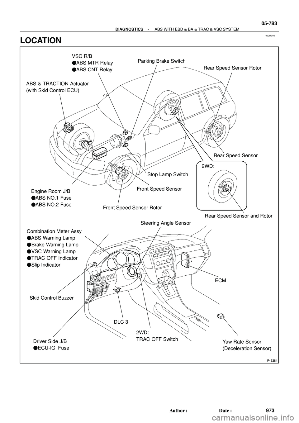
05CD0-06
F46284
Rear Speed Sensor and Rotor
ABS & TRACTION Actuator
(with Skid Control ECU)
Engine Room J/B
�ABS NO.1 Fuse
�ABS NO.2 Fuse
Combination Meter Assy
�ABS Warning Lamp
�Brake Warning Lamp
�VSC Warning Lamp
�TRAC OFF Indicator
�Slip Indicator
Driver Side J/B
�ECU-IG FuseStop Lamp Switch
2WD:
TRAC OFF Switch DLC 3
VSC R/B
�ABS MTR Relay
�ABS CNT Relay
Yaw Rate Sensor
(Deceleration Sensor)
ECM
Steering Angle Sensor
Skid Control Buzzer
Front Speed Sensor
Front Speed Sensor Rotor
2WD:
Parking Brake Switch
Rear Speed Sensor Rear Speed Sensor Rotor
- DIAGNOSTICSABS WITH EBD & BA & TRAC & VSC SYSTEM
05-783
973 Author�: Date�:
LOCATION

M OVERALL ELECTRICAL WIRING DIAGRAM
34
2 1
33 HIGHLANDER
1C 6
40A
AM1
1A 1
42140A ALT
30A CDS
30A RDI
1 2
5 322
2 2
1 2
M2 1
5 3
4 22
22 2
2G 282G
2F 4
2 3
EH2 1
5 3 22
22")

M OVERALL ELECTRICAL WIRING DIAGRAM
1
234
36 HIGHLANDER
Power SourceRear Heater2
1B140A
AL T40A AM1
2ACC
IG1 AM1 4
1C
6
1A 1
10A HEATER
71C
1G 8
15A RR HTR
2
2
3 5
2 1 9BH1")