Page 1412 of 2572

G30835G32449
E4
Electronically Controlled
Transmission Pattern Select SW
*
SNOW B9 15Multiplex Network
Body ECU
(*) Pattern Select Switch (ECT SNOW Switch)
When the ECT SNOW switch is pushed, the switch contact is made and the ECT SNOW mode is selected.
To cancel the ECT SNOW mode, push the ECT SNOW switch once again. The ECT SNOW mode is automati-
cally cancelled when the ignition switch is turned ºOFFº.Y
3 4 W-B
3D Center J/B
8
3F 13
W-B
IB
- DIAGNOSTICSELECTRONIC CONTROLLED AUTOMATIC
TRANSAXLE [ECT] (U241E/U140F)05-983
1173 Author�: Date�:
2005 HIGHLANDER REPAIR MANUAL (RM1144U)
PATTERN SELECT SWITCH CIRCUIT
CIRCUIT DESCRIPTION
Multiplex network body ECU receives pattern select switch information, and sends it through the multiplex
communication system to the ECM.
ECT SNOW is the system that operates the throttle motor to control engine output to reduce skidding of the
driving wheels, guarantee takeoff acceleration, driving straightness and turning stability.
WIRING DIAGRAM
05ITR-02
Page 1416 of 2572

A93865Purge VSV
EVAP Hose
(To Throttle Body)
EVAP Hose
(From Canister)
Vent ValveCanister
Air Filter
Pump ModulePressure Sensor
Vacuum Pump
Purge Line
Refueling Valve
Fuel Tank
Fuel Cap
Location of EVAP (Evaporative Emission) system:
A93866
EVAP System Circuit
Intake Manifold
Purge VSV
Cut-of f Valve Roll-over Valve
CanisterAir FilterFuel Cap
Service Port
Air Cleaner
Restrictor (0.08 inch)
Refueling Valve Throttle Valve
ECM
Soak Timer
Pump Module (refer to fig. 1)
Fuel Tank 05-318
- DIAGNOSTICSSFI SYSTEM (2AZ-FE)
508 Author�: Date�:
2005 HIGHLANDER REPAIR MANUAL (RM1144U)
CIRCUIT DESCRIPTION
While the engine is running, if a predetermined condition (closed-loop, etc.) is met, the purge VSV is opened
by the ECM and stored fuel vapors in the canister are purged to the intake manifold. The ECM changes the
duty cycle ratio of the purge VSV to control purge flow volume.
The purge flow volume is also determined by the intake manifold pressure.
Atmospheric pressure is allowed
into the canister through the vent valve to ensure that the purge flow is maintained when the negative pres-
sure (vacuum) is applied to the canister.
The following two monitors run to confirm appropriate EVAP system operation.
Page 1429 of 2572

G36776
ON
Puge VSV Stuck Closed
4/5
ONON
Purge VSV
Vent Valve
Vacuum Pump
EVAP Pressure
Positive
Negative
Steps
(Reference)TimeON: Open
OFF: Closed
OFF: Vent ON: Closed
OK
10
sec
Leak Pressure First 0.02 inch
Standard
- DIAGNOSTICSSFI SYSTEM (2AZ-FE)
05-331
521 Author�: Date�:
2005 HIGHLANDER REPAIR MANUAL (RM1144U)
9 PERFORM EVAP SYSTEM CHECK(STEP 4/5)
(a) Check the EVAP pressure in step 4/5.
DTCs*Test ResultsSuspected Trouble AreasProceed To
'
EVAP pressure increases by 0.3 kPa (2.25 mmHg)
or more within 10 seconds of proceeding from step
3/5 to step 4/5
Not yet determinedA
P0441
EVAP pressure increases by 0.3 kPa (2.25 mmHg)
or more within 10 seconds of proceeding from step
3/5 to step 4/5Problems in EVAP hose between pure VSV and
throttle bodyB
P0441
Variation in EVAP pressure is less than 0.3 kPa
(2.25 mmHg) for 10 seconds, after proceeding from
step 3/5 to step 4/5
Purge VSV stuck closedC
*: The DTCs relating to the EVAP system displayed on a hand-held tester when checking.
B Go to step 15
C Go to step 12
A
Page 1432 of 2572
A85254
Purge VSV
Hose (to canister)
05-334
- DIAGNOSTICSSFI SYSTEM (2AZ-FE)
524 Author�: Date�:
2005 HIGHLANDER REPAIR MANUAL (RM1144U)
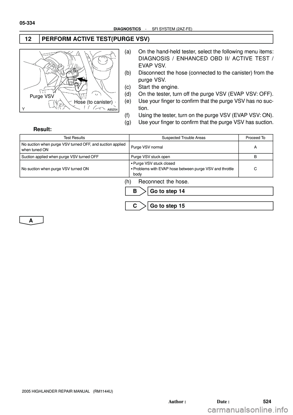
12 PERFORM ACTIVE TEST(PURGE VSV)
(a) On the hand-held tester, select the following menu items:
DIAGNOSIS / ENHANCED OBD II/ ACTIVE TEST /
EVAP VSV.
(b) Disconnect the hose (connected to the canister) from the
purge VSV.
(c) Start the engine.
(d) On the tester, turn off the purge VSV (EVAP VSV: OFF).
(e) Use your finger to confirm that the purge VSV has no suc-
tion.
(f) Using the tester, turn on the purge VSV (EVAP VSV: ON).
(g) Use your finger to confirm that the purge VSV has suction.
Result:
Test ResultsSuspected Trouble AreasProceed To
No suction when purge VSV turned OFF, and suction applied
when tuned ONPurge VSV normalA
Suction applied when purge VSV turned OFFPurge VSV stuck openB
No suction when purge VSV turned ON
�Purge VSV stuck closed
�Problems with EVAP hose between purge VSV and throttle
body
C
(h) Reconnect the hose.
B Go to step 14
C Go to step 15
A
Page 1434 of 2572
A85261
Purge VSV
Hose (to throtlle body)
A68357
A
B Purge VSV
05-336
- DIAGNOSTICSSFI SYSTEM (2AZ-FE)
526 Author�: Date�:
2005 HIGHLANDER REPAIR MANUAL (RM1144U)
15 CHECK EVAP HOSE(PURGE VSV - THROTTLE BODY)
(a) Disconnect the hose (connected to the throttle body) from
the purge VSV.
(b) Start the engine.
(c) Use your finger to confirm that the hose has suction.
Result:
Test ResultsSuspected Trouble AreasProceed To
Suction appliedEVAP hose between purge VSV and throttle body
normalA
No suction
�Throttle body
�EVAP hose between purge VSV and throttle
body
B
(d) Reconnect the hose.
B Go to step 26
A
16 NSPECT VACUUM SWITCHING VALVE ASSY NO.1(PURGE VSV)
(a) Remove the purge VSV.
(b) Apply battery voltage to the terminals of the purge VSV.
(c) Using an air gun, confirm that air flows from port A to port
B.
Result:
Test ResultsSuspected Trouble AreasProceed To
Air flowedPurge VSV normalA
No air flowPurge VSVB
(d) Install the purge VSV.
B Go to step 31
A
Page 1440 of 2572
A85258
Wire Harness Side
C17
Canister
05-342
- DIAGNOSTICSSFI SYSTEM (2AZ-FE)
532 Author�: Date�:
2005 HIGHLANDER REPAIR MANUAL (RM1144U)
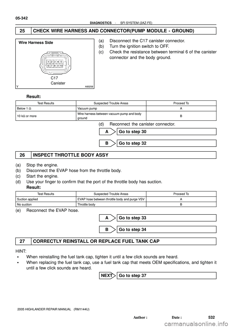
25 CHECK WIRE HARNESS AND CONNECTOR(PUMP MODULE - GROUND)
(a) Disconnect the C17 canister connector.
(b) Turn the ignition switch to OFF.
(c) Check the resistance between terminal 6 of the canister
connector and the body ground.
Result:
Test ResultsSuspected Trouble AreasProceed To
Below 1 WVacuum pumpA
10 kW or moreWire harness between vacuum pump and body
groundB
(d) Reconnect the canister connector.
A Go to step 30
B Go to step 32
26 INSPECT THROTTLE BODY ASSY
(a) Stop the engine.
(b) Disconnect the EVAP hose from the throttle body.
(c) Start the engine.
(d) Use your finger to confirm that the port of the throttle body has suction.
Result:
Test ResultsSuspected Trouble AreasProceed To
Suction appliedEVAP hose between throttle body and purge VSVA
No suctionThrottle bodyB
(e) Reconnect the EVAP hose.
A Go to step 33
B Go to step 34
27 CORRECTLY REINSTALL OR REPLACE FUEL TANK CAP
HINT:
�When reinstalling the fuel tank cap, tighten it until a few click sounds are heard.
�When replacing the fuel tank cap, use a fuel tank cap that meets OEM specifications, and tighten it
until a few click sounds are heard.
NEXT Go to step 37
Page 1442 of 2572

A85254
Purge VSV
05-344
- DIAGNOSTICSSFI SYSTEM (2AZ-FE)
534 Author�: Date�:
2005 HIGHLANDER REPAIR MANUAL (RM1144U)
31 REPLACE VACUUM SWITCHING VALVE ASSY NO.1(PURGE VSV)
(a) Disconnect the connector and the hoses from the purge
VSV.
(b) Remove the purge VSV.
(c) Install a new purge VSV.
(d) Reconnect the connector and hoses.
NEXT Go to step 37
32 REPAIR OR REPLACE WIRE HARNESS AND CONNECTOR
In case that the exhaust tail pipe is removed, go to the next step before installing it.
NEXT Go to step 37
33 REPLACE EVAP HOSE(THROTTLE BODY - PURGE VSV)
NEXT Go to step 37
34 INSPECT THROTTLE BODY ASSY
(a) Remove the throttle body (see page 10-6).
(b) Check that there is no clog in the EVAP purge port of the throttle body. If necessary, replace the throttle
body.
NEXT Go to step 37
35 REPLACE ECM (see page 10-9)
NEXT Go to step 37
36 REPAIR OR REPLACE PARTS AND COMPONENTS INDICATED BY OUTPUT DTCS
(a) Repair the malfunctioning areas indicated by the DTCs that had been confirmed when the vehicle was
brought in.
NEXT Go to step 37
Page 1658 of 2572
A54396
+B (+) Wire Harness Side
M1
MAF Meter
05-84
- DIAGNOSTICSSFI SYSTEM (2AZ-FE)
274 Author�: Date�:
2005 HIGHLANDER REPAIR MANUAL (RM1144U)
INSPECTION PROCEDURE
HINT:
Read freeze frame data using the hand-held tester or the OBD II scan tool. Freeze frame data records the
engine conditions when a malfunction is detected. When troubleshooting, freeze frame data can help deter-
mine if the vehicle was running or stopped, if the engine was warmed up or not, if the air-fuel ratio was lean
or rich, and other data from the time the malfunction occurred.
1 READ VALUE OF HAND-HELD TESTER OR OBD II SCAN TOOL (MAF RATE)
(a) Connect the hand-held tester or the OBD II scan tool to the DLC3.
(b) Start the engine.
(c) Push the hand-held tester or the OBD II scan tool main switch ON.
(d) On the hand-held tester or the OBD II scan tool, enter the following menus: DIAGNOSIS / ENHANCED
OBD II / DATA LIST / ALL / MAF. Read the values.
Result:
Air Flow Rate (gm/second)Proceed to
0.0A
271.0 or moreB
MAF rate greater than 1 but less than 270.0 *C
HINT:
*: The value must change when the throttle valve is opened or closed.
B Go to step 6
C CHECK FOR INTERMITTENT PROBLEMS
(See page 05-9)
A
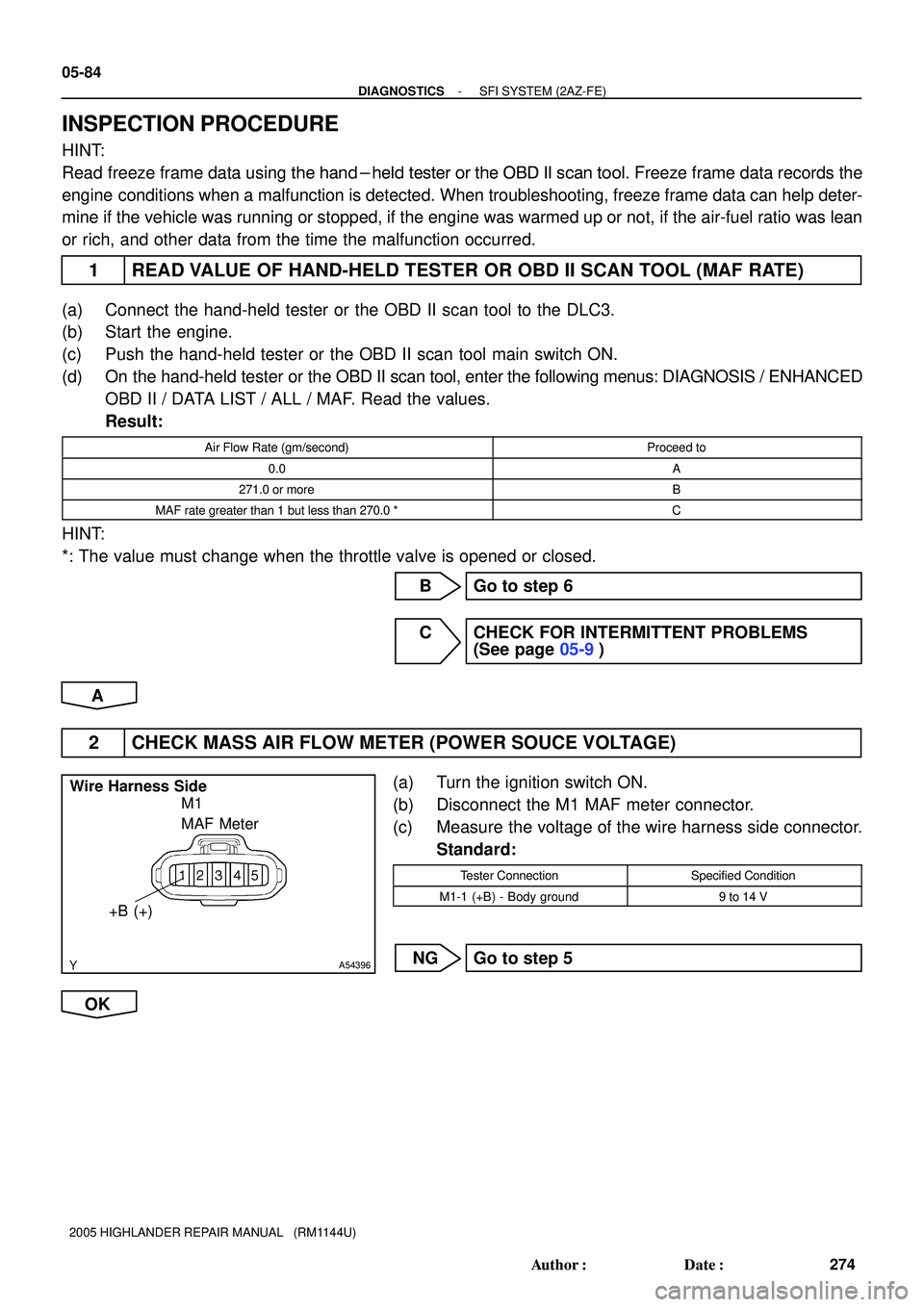
2 CHECK MASS AIR FLOW METER (POWER SOUCE VOLTAGE)
(a) Turn the ignition switch ON.
(b) Disconnect the M1 MAF meter connector.
(c) Measure the voltage of the wire harness side connector.
Standard:
Tester ConnectionSpecified Condition
M1-1 (+B) - Body ground9 to 14 V
NG Go to step 5
OK
