Page 1 of 2572

BASIC FUNCTIONS
1
BASIC FUNCTIONS
Basic information before operation
Touch switch operation2 . . . . . . . . . . . . . . . . . . . . . . . . . . . . . . . . . . . . . . . . . . . . . . . .
Inputting letters and numbers2 . . . . . . . . . . . . . . . . . . . . . . . . . . . . . . . . . . . . . . . . . . .
Current position display4 . . . . . . . . . . . . . . . . . . . . . . . . . . . . . . . . . . . . . . . . . . . . . . . .
Screen scroll operation (one-touch scroll)5 . . . . . . . . . . . . . . . . . . . . . . . . . . . . . . . .
Map scale8 . . . . . . . . . . . . . . . . . . . . . . . . . . . . . . . . . . . . . . . . . . . . . . . . . . . . . . . . . . .
Orientation of the map9 . . . . . . . . . . . . . . . . . . . . . . . . . . . . . . . . . . . . . . . . . . . . . . . . .
Limitations of the navigation system9 . . . . . . . . . . . . . . . . . . . . . . . . . . . . . . . . . . . . .
Map database information and updates12 . . . . . . . . . . . . . . . . . . . . . . . . . . . . . . . . .
SECTION I
Page 12 of 2572

BASIC FUNCTIONS
12
Map database information and
updates
This system uses the maps of DENSO.
W GDT, Geographic Data Technology,
Inc.
Data by infoUSA Copyright W2003, All
Rights Reserved.
W 2003 VISA Corporation
National Research Bureau W2003
END USER LICENSE AGREEMENT
PLEASE READ THIS AGREEMENT
CAREFULLY BEFORE USING THE
NAVIGATION SYSTEM
THIS IS A LICENSE AGREEMENT FOR
YOUR COPY OF THE MAP DATABASE
(The DATABASEº), ORIGINALLY
MADE BY Geographic Data Technology,
Inc. (GDTº), USED IN THE
NAVIGATION SYSTEM. BY USING THE
DATABASE, YOU ACCEPT AND
AGREE TO ALL TERMS AND
CONDITIONS SET FORTH BELOW.
OWNERSHIP
The DATABASE and the copyrights and
intellectual property or neighboring rights
therein are owned by GDT or its
licensors.
LICENSE GRANT
GDT grants you a non-exclusive license
to use your copy of the DATABASE for
your personal use or for use in your
business' internal operations. This
license does not include the right to grant
sub-licenses.
LIMITATIONS ON USE
The DATABASE is restricted for use in
the specific system for which it was
created. Except to the extent explicitly
permitted by mandatory laws, you may
not extract or re-utilize any portion of the
contents of the DATABASE, nor
reproduce, copy, modify, adapt,
translate, disassemble, decompile, or
reverse engineer any portion of the
DATABASE.
TRANSFER
You may not transfer the DATABASE to
third parties, except together with the
system for which it was created, provided
that you do not retain any copy of the
DATABASE, and provided that the
transferee agrees to all terms and
conditions of this AGREEMENT.DISCLAIMER OF WARRANTY
GDT does not warrant or make any
representations regarding, either
express or implied, regarding the use or
results of the use of the DATABASE in
terms of its correctness, accuracy,
reliability, or otherwise, and expressly
disclaims any implied warranties of
quality, performance, merchantability,
fitness for a particular purpose or
non-infringement. GDT does not
warrant that the DATABASE is or will be
error free. No oral or written information
or advice provided by GDT, your supplier
or any other person shall create a
warranty.
Page 16 of 2572

BASIC FUNCTIONS
16
There are two types of areas available for
route guidance. In one type of area, pri-
marily around metropolitan centers, de-
tailed route guidance is available for the
entire area. In the other type of area, all
roads are displayed on the map but route
guidance is limited. The navigation route
might lack precision because the data (no
right turns, one-way traffic, etc.) is not
complete. It is still possible to reach the
destination by following the arrow direc-
tion and distance as shown on the bottom
left of the screen. The arrow points in the
direction of the destination. The distance
shown is as measured in a straight line
from the current vehicle position to the
destination area.
In order to provide you with as accurate map
information as possible, we are always gath-
ering information such as road repairs and
doing site investigation. However, the names
of roads, streets, facilities, and their locations
are often changed. In some places, construc-
tion on roads may be in progress. For that
reason, information on some areas in this
system might be different from the actual
location.
The map database is normally updated once
a year. Contact your dealer for information
about the availability and pricing of an
update.
�To confirm the database version and
disc coverage area
1. Push the
MENUº button.
2. Touch the Map DVDº switch.
Make sure the version of the database on this
screen. (The database version on the screen
above may be different from the actual
screen.)
Page 885 of 2572
I38223
05-1806
- DIAGNOSTICSNAVIGATION SYSTEM
1996 Author�: Date�:
2005 HIGHLANDER REPAIR MANUAL (RM1144U)
ILLUMINATION FOR PANEL SWITCH DOES NOT COME ON WITH
TAIL SWITCH ON
INSPECTION PROCEDURE
1 DISPLAY CHECK MODE(VEHICLE SIGNAL CHECK MODE)
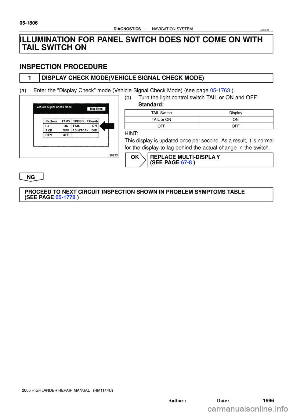
(a) Enter the ºDisplay Checkº mode (Vehicle Signal Check Mode) (see page 05-1763).
(b) Turn the light control switch TAIL or ON and OFF.
Standard:
TAIL SwitchDisplay
TAIL or ONON
OFFOFF
HINT:
This display is updated once per second. As a result, it is normal
for the display to lag behind the actual change in the switch.
OK REPLACE MULTI-DISPLA Y
(SEE PAGE 67-8)
NG
PROCEED TO NEXT CIRCUIT INSPECTION SHOWN IN PROBLEM SYMPTOMS TABLE
(SEE PAGE 05-1778)
05ISG-02
Page 893 of 2572
I38228
05-1814
- DIAGNOSTICSNAVIGATION SYSTEM
2004 Author�: Date�:
2005 HIGHLANDER REPAIR MANUAL (RM1144U)
3 NAVIGATION CHECK MODE(VEHICLE SENSORS)
(a) Move the shift lever to the R or P position.
Standard:
Shift leverDisplay
POFF
RON
HINT:
The display is updated once per second. As a result, it is normal
for the display to lag behind the actual change in the switch.
NG GO TO ºREVERSE SIGNAL CIRCUITº IN THE
FLOW CHART (SEE PAGE 05-1844)
OK
PROCEED TO NEXT CIRCUIT INSPECTION SHOWN IN PROBLEM SYMPTOMS TABLE
(SEE PAGE 05-1778)
Page 895 of 2572

VEHICLE POSITION MARK IS NOT UPDATED
INSPECTION PROCEDURE
1 CHECK THE MAP DISC
(a) C")
I38584
I38228
05-1816
- DIAGNOSTICSNAVIGATION SYSTEM
2006 Author�: Date�:
2005 HIGHLANDER REPAIR MANUAL (RM1144U)
VEHICLE POSITION MARK IS NOT UPDATED
INSPECTION PROCEDURE
1 CHECK THE MAP DISC
(a) Check that the map disc is not deformed or cracked.
OK: No deformations or cracks appear on the map
disc.
NG REPLACE THE MAP DISC
OK
2 CHECK THE MAP DISPLAY
(a) Check if a touch scroll can be performed on the map display.
OK: Touch scroll can be performed.
NG PROCEED TO NEXT CIRCUIT INSPECTION
SHOWN IN PROBLEM SYMPTOMS TABLE
(SEE PAGE 05-1778)
OK
3 NAVIGATION CHECK MODE(VEHICLE SENSORS)
(a) Enter the ºNavigation Checkº mode (Vehicle Sensors) (see page 05-1765).
(b) While driving, compare the ºSPEEDº indicator to the read-
ing on the speedometer. Check if these readings are al-
most the same.
OK: The readings are almost the same.
NG GO TO ºSPEED SIGNAL CIRCUIT (NAVIGATION
ECU - COMBINATION METER ASSY)º IN THE
FLOW CHART (SEE PAGE 05-1838)
OK
PROCEED TO NEXT CIRCUIT INSPECTION SHOWN IN PROBLEM SYMPTOMS TABLE
(SEE PAGE 05-1778)
05ISO-02
Page 1377 of 2572
05IS2-02
I38215
I38222
I38223
- DIAGNOSTICSNAVIGATION SYSTEM
05-1763
1953 Author�: Date�:
2005 HIGHLANDER REPAIR MANUAL (RM1144U)
DISPLAY CHECK MODE (VEHICLE SIGNAL CHECK)
HINT:
�This mode checks the vehicle signal status input to the multi-display.
�Illustrations may differ from the actual vehicle depending on the device settings and options. There-
fore, some detailed areas may not be shown exactly the same as on the actual vehicle.
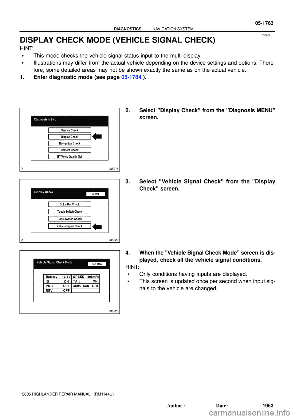
1. Enter diagnostic mode (see page 05-1784).
2. Select ºDisplay Checkº from the ºDiagnosis MENUº
screen.
3. Select ºVehicle Signal Checkº from the ºDisplay
Checkº screen.
4. When the ºVehicle Signal Check Modeº screen is dis-
played, check all the vehicle signal conditions.
HINT:
�Only conditions having inputs are displayed.
�This screen is updated once per second when input sig-
nals to the vehicle are changed.
Page 1382 of 2572

(e) LAN Monitor (Individual) Screen
Screen Description
DisplayConte")
I38590
*1
*2
*3
*4
*5*6
I38591
- DIAGNOSTICSNAVIGATION SYSTEM
05-1771
1961 Author�: Date�:
2005 HIGHLANDER REPAIR MANUAL (RM1144U)
(e) LAN Monitor (Individual) Screen
Screen Description
DisplayContents
Device name/*1Target device
Segment/*2Target logical address
DTC/*3DTC (Diagnostic Trouble Code)
Sub-Code (device address)/*4Physical address stored with DTC. (If there is no address, nothing is displayed.)
Connection check No./*5Connection check number stored with DTC.
DTC occurrence/*6Number of times the same DTC has been recorded.
2. DISPLAY CHECK
(a) Vehicle Signal Check Mode Screen
Screen Description
NameContents
BatteryBattery voltage is displayed.
PKBParking brake ON/OFF state is displayed.
REVReverse signal ON/OFF state is displayed.
IGIG switch ON/OFF state is displayed.
ADIM/TCANBrightness state DIM (with)/ BRIGHT (without) is displayed.
SPEEDThe vehicle speed, displayed in km/h.
TAILTAIL signal (Head lamp dimmer switch) ON/OFF state is displayed.
HINT:
�Only items sending a vehicle signal will be displayed.
�This screen is updated once per second when input signals to the vehicle are changed.