Page 741 of 2572
F46304
Combination Meter
Passenger Side J/BABS C11
Instrument Panel J/BSkid Control ECU with Actuator
I15
Ignition SW
F7
FL BlockC11 IF2
IL1 IC4 S27
S27 S27 4E
4H 4JJ6
J/C
IC4
IC1 1A
1C 1D
1G
1C 1C ECU-IG
IGN
AM1IG1 4M
IG2AM1
AM2WA
IG1
GND1
EA EB ALT
AM2
J4
J/C FL MAIN
Battery1
24 6
7 9
10 13
1729
4
446
4
62
10
32 12
12
1 E P W SB R-L
P
ESB
GRB-R
G
GR
W
Y
L-Y WB
W-B Y
W
AW-B 167 10
1
6 05-840
- DIAGNOSTICSABS WITH EBD & BA & TRAC & VSC SYSTEM
1030 Author�: Date�:
ABS WARNING LIGHT CIRCUIT (REMAINS ON)
CIRCUIT DESCRIPTION
During DTC read by SST (CHECK WIRE), if the ABS warning light remains on, troubleshoot by following
this inspection flow.
WIRING DIAGRAM
05CDG-1 1
Page 745 of 2572
F50610
Skid Control ECU with Actuator Combination Meter
B4
Brake Warning SW
Passenger Side J/B
Instrument Panel J/B
I15
Ignition SW
F7
FL Block Brake
IGN
AM2BRL
PKB
AM2 IG2
FL MAIN
BatteryC11 IF3 IC4 S27
IL1
S27 C12
C12IF3
IC4
4E 4M
1C
1G4J
4MIC4
IC1Passenger Side J/B
P3
Parking
Brake SW J4
J/C
EB1
2
3 46
791011 13
1644
15
1
28 J6
J/C
11
9
16
6
1
10
1 1
1 B
PR V
W YSB
P
EER-B SB
R-W
LG
B
A L-Y GRW W-B
LG-B
05-854
- DIAGNOSTICSABS WITH EBD & BA & TRAC & VSC SYSTEM
1044 Author�: Date�:
BRAKE WARNING LIGHT CIRCUIT
CIRCUIT DESCRIPTION
The BRAKE warning light comes on when the brake fluid is insufficient, the parking brake is applied or the
EBD is defective.
WIRING DIAGRAM
05F1V-09
Page 750 of 2572
F46304
Combination Meter
Passenger Side J/BABS C11
Instrument Panel J/BSkid Control ECU with Actuator
I15
Ignition SW
F7
FL BlockC11 IF2
IL1 IC4 S27
S27 S27 4E
4H 4JJ6
J/C
IC4
IC1 1A
1C 1D
1G
1C 1C ECU-IG
IGN
AM1IG1 4M
IG2AM1
AM2WA
IG1
GND1
EA EB ALT
AM2
J4
J/C FL MAIN
Battery1
24 6
7 9
10 13
1729
4
446
4
62
10
32 12
12
1 E P W SB R-L
P
ESB
GRB-R
G
GR
W
Y
L-Y WB
W-B Y
W
AW-B 167 10
1
6 05-844
- DIAGNOSTICSABS WITH EBD & BA & TRAC & VSC SYSTEM
1034 Author�: Date�:
ABS WARNING LIGHT CIRCUIT (DOES NOT LIGHT UP)
WIRING DIAGRAM
05F1T-06
Page 754 of 2572
BODY PANEL REPLACEMENT
F16777
POINT
1 Inspect the fitting of the quarter panel, back door and rear combination light, etc., before welding, since this
affects the appearance of the finish.BP-51
INSTALLATION
�Temporarily install the new parts and measure each part of the new parts in accordance with the body dimension
diagram. (See the body dimension diagram)
�Inspect the fitting of the related parts around the new parts before welding. This affects the appearance of the
finish.
�After welding, apply the polyurethane foam to the corresponding parts.
�After welding, apply body sealer and under-coating to the corresponding parts.
�After applying the top coat layer, apply anti-rust agent to the inside of the necked section structural weld spots.
Page 757 of 2572
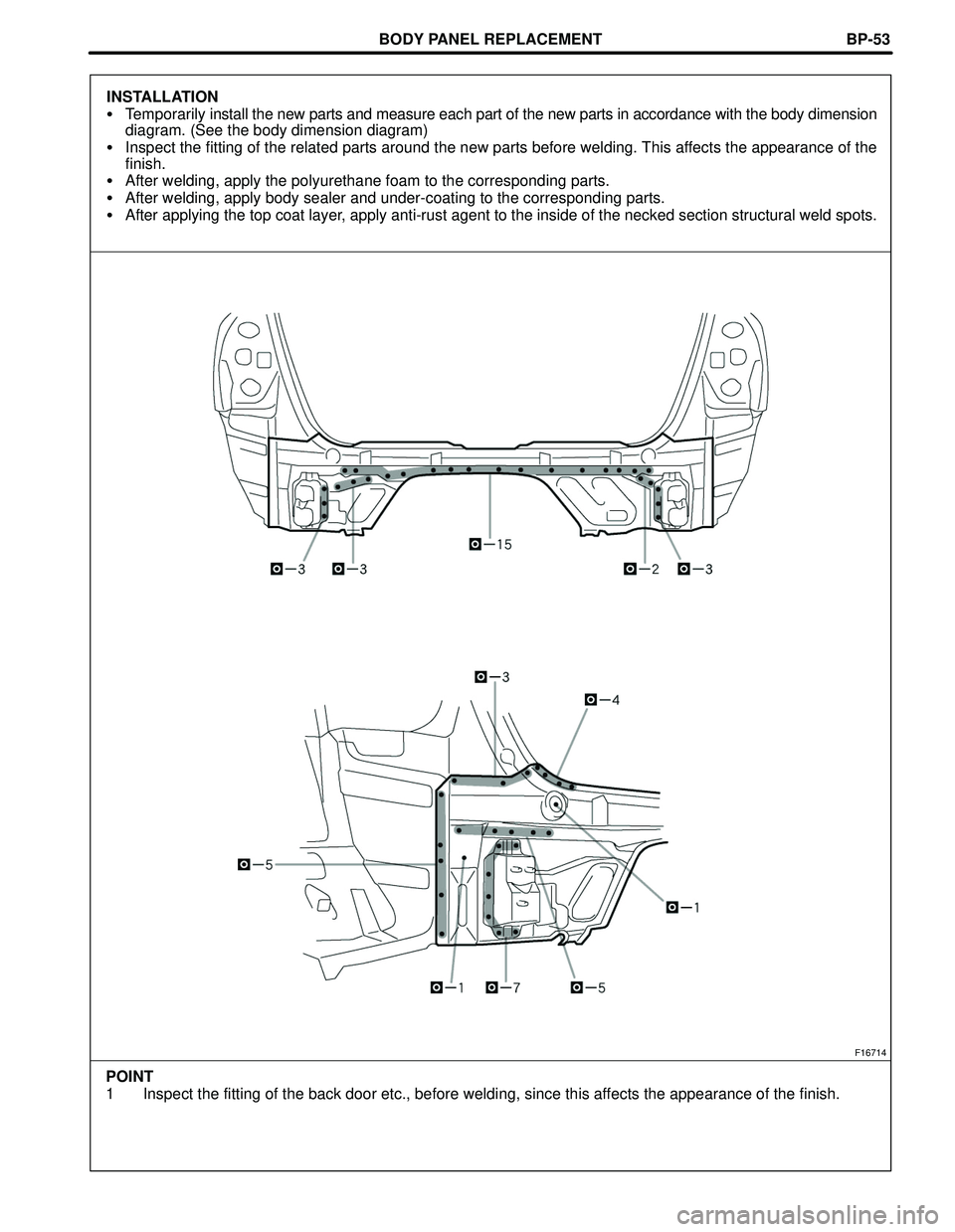
BODY PANEL REPLACEMENT
F16714
POINT
1 Inspect the fitting of the back door etc., before welding, since this affects the appearance of the finish.BP-53
INSTALLATION
�Temporarily install the new parts and measure each part of the new parts in accordance with the body dimension
diagram. (See the body dimension diagram)
�Inspect the fitting of the related parts around the new parts before welding. This affects the appearance of the
finish.
�After welding, apply the polyurethane foam to the corresponding parts.
�After welding, apply body sealer and under-coating to the corresponding parts.
�After applying the top coat layer, apply anti-rust agent to the inside of the necked section structural weld spots.
Page 771 of 2572

F40566
Skid Control ECU with Actuator
2
1
1817
FL+
FL- A4
ABS Speed Sensor
Front LH
43
FR+
FR- A5
ABS Speed Sensor
Front RHS27 R-Y
LG
O
P 2
1S27
S27
S27
- DIAGNOSTICSABS WITH EBD & BA & TRAC & VSC SYSTEM
05-789
979 Author�: Date�:
WIRING DIAGRAM
INSPECTION PROCEDURE
HINT:
Start the inspection from step 1 when using the hand-held tester and start from step 3 when not using the
hand-held tester.
1 READ VALUE OF HAND-HELD TESTER(FRONT SPEED SENSOR)
(a) Connect the hand-held tester to the DLC3.
(b) Start the engine.
(c) Select the DATA LIST mode on the hand-held tester.
(d) Check that there is no difference between the speed value output from the speed sensor displayed
on the hand-held tester and the speed value displayed on the speedometer when driving the vehicle.
ItemMeasurement Item /
Range (Display)Normal Condition
WHEEL SPD FR
Wheel speed sensor (FR) reading /
min.: 0 km/h (0 MPH, max.: 326 km/h
(202 MPH)
Actual wheel speed
WHEEL SPD FL
Wheel speed sensor (FL) reading /
min.: 0 km/h (0 MPH, max.: 326 km/h
(202 MPH)
Actual wheel speed
OK:
There is almost no difference from the displayed speed value.
HINT:
There is tolerance of + 10 % in the speedometer indication.
NG Go to step 3
OK
Page 777 of 2572

F46312
Skid Control ECU with Actuator
1 2206
S27
A25
ABS Speed Sensor
Rear RH
5 19 A24
ABS Speed Sensor
Rear LH
1 12
IO2
6 15 16
7
RR-
RR+ RL-
RL+ IC2 IA1
1 2IO2IA1 IC2
IC2
IC2 2
2S27
S27
S27 G
L O
PR V
Y R
GRBR
Y Y-G
- DIAGNOSTICSABS WITH EBD & BA & TRAC & VSC SYSTEM
05-795
985 Author�: Date�:
DTC C0210/33 RIGHT REAR SPEED SENSOR
DTC C0215/34 LEFT REAR SPEED SENSOR
DTC C1238/38 FOREIGN MATTER IS ATTACHED ON TIP OF
RIGHT REAR SENSOR
DTC C1239/39 FOREIGN MATTER IS ATTACHED ON TIP OF
LEFT REAR SENSOR
CIRCUIT DESCRIPTION
Refer to DTC C0200/31, C0205/32, C1235/35, C1236/36 on page 05-788.
DTC No.DTC Detecting ConditionTrouble Area
C0210/33
C0215/34
(1) All the following conditions continues for at least 1 se-
cond.
�Vehicle speed is more than 6 mph (10 km/h).
�Open or short in vehicle speed sensor signal circuit of
faulty wheel continues for 1 second or more.
(2) Momentary interruption of the sensor signal of faulty
wheel has occurred 7 times or more.
(3) Sensor signal circuit is open for 0.5 seconds.
�Right rear and left rear speed sensor
�Each speed sensor circuit
�Sensor rotor
�Sensor installation
C1238/38
C1239/39All the following conditions for at least 5 seconds.
�Vehicle speed is more than 12 mph (20 km/h).
�Vehicle speed sensor signal receives.�Right rear and left rear speed sensor
�Each speed sensor
�Sensor installation
HINT:
�DTC C0210/33 and C1238/38 are for the right rear speed sensor.
�DTC C0215/34 and C1239/39 are for the left rear speed sensor.
WIRING DIAGRAM
05H3B-03
Page 785 of 2572
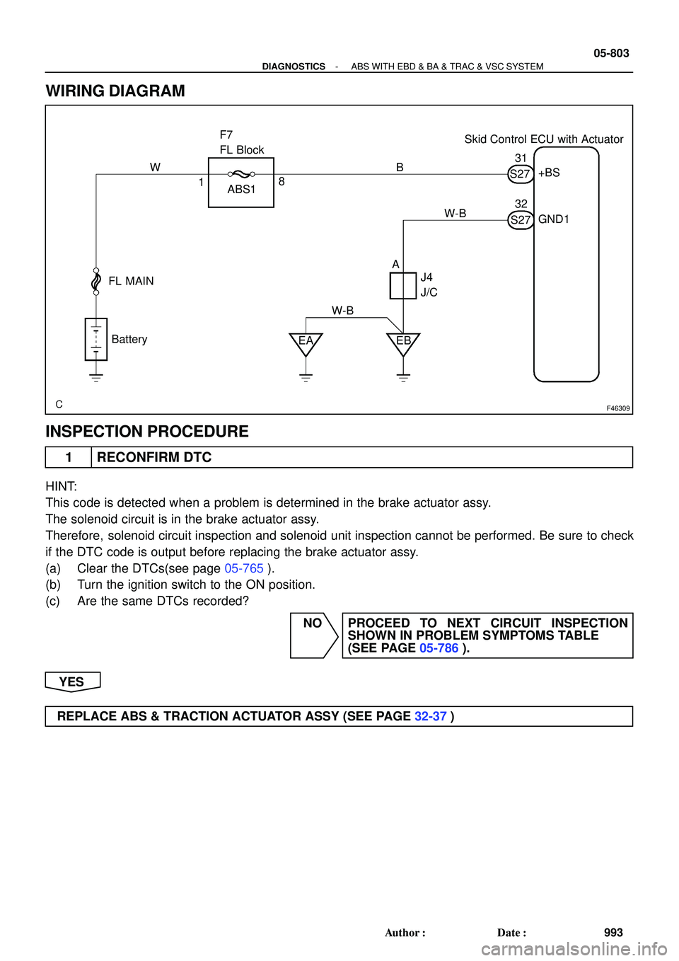
F46309
Skid Control ECU with Actuator F7
FL Block
FL MAIN
Battery
EA EB ABS1+BS
GND1
J4
J/C 1831
32
AB W
W-BS27
S27 W-B
- DIAGNOSTICSABS WITH EBD & BA & TRAC & VSC SYSTEM
05-803
993 Author�: Date�:
WIRING DIAGRAM
INSPECTION PROCEDURE
1 RECONFIRM DTC
HINT:
This code is detected when a problem is determined in the brake actuator assy.
The solenoid circuit is in the brake actuator assy.
Therefore, solenoid circuit inspection and solenoid unit inspection cannot be performed. Be sure to check
if the DTC code is output before replacing the brake actuator assy.
(a) Clear the DTCs(see page 05-765).
(b) Turn the ignition switch to the ON position.
(c) Are the same DTCs recorded?
NO PROCEED TO NEXT CIRCUIT INSPECTION
SHOWN IN PROBLEM SYMPTOMS TABLE
(SEE PAGE 05-786).
YES
REPLACE ABS & TRACTION ACTUATOR ASSY (SEE PAGE 32-37)