D01563
D25081
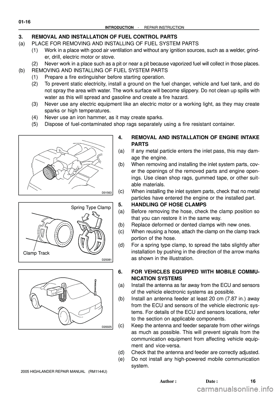
Spring Type Clamp
Clamp Track
D20025
01-16
- INTRODUCTIONREPAIR INSTRUCTION
16 Author�: Date�:
2005 HIGHLANDER REPAIR MANUAL (RM1144U)
3. REMOVAL AND INSTALLATION OF FUEL CONTROL PARTS
(a) PLACE FOR REMOVING AND INSTALLING OF FUEL SYSTEM PARTS
(1) Work in a place with good air ventilation and without any ignition sources, such as a welder, grind-
er, drill, electric motor or stove.
(2) Never work in a place such as a pit or near a pit because vaporized fuel will collect in those places.
(b) REMOVING AND INSTALLING OF FUEL SYSTEM PARTS
(1) Prepare a fire extinguisher before starting operation.
(2) To prevent static electricity, install a ground on the fuel changer, vehicle and fuel tank, and do
not spray the area with water. The work surface will become slippery. Do not clean up spills with
water as this will spread and gasoline and create a fire hazard.
(3) Never use any electric equipment like an electric motor or a working light, as they may create
sparks or high temperatures.
(4) Never use an iron hammer, as it may create sparks.
(5) Dispose of fuel-contaminated shop rags separately using a fire resistant container.
4. REMOVAL AND INSTALLATION OF ENGINE INTAKE
PARTS
(a) If any metal particle enters the inlet pass, this may dam-
age the engine.
(b) When removing and installing the inlet system parts, cov-
er the openings of the removed parts and engine open-
ings. Use clean shop rags, gummed tape, or other suit-
able materials.
(c) When installing the inlet system parts, check that no metal
particles have entered the engine or the installed part.
5. HANDLING OF HOSE CLAMPS
(a) Before removing the hose, check the clamp position so
that you can restore it in the same way.
(b) Replace deformed or dented clamps with new ones.
(c) When reusing a hose, attach the clamp on the clamp track
portion of the hose.
(d) For a spring type clamp, to spread the tabs slightly after
installation by pushing in the direction of the arrow marks
as shown in the illustration.
6. FOR VEHICLES EQUIPPED WITH MOBILE COMMU-
NICATION SYSTEMS
(a) Install the antenna as far away from the ECU and sensors
of the vehicle electronic systems as possible.
(b) Install an antenna feeder at least 20 cm (7.87 in.) away
from the ECU and sensors of the vehicle electronic sys-
tems. For details of the ECU and sensors locations, refer
to the section on applicable components.
(c) Keep the antenna and feeder separate from other wirings
as much as possible. This will prevent signals from the
communication equipment from affecting vehicle equip-
ment and vice-versa.
(d) Check that the antenna and feeder are correctly adjusted.
(e) Do not install any high-powered mobile communication
system.
![TOYOTA HIGHLANDER 2001 Service Repair Manual F14883
POINT
1 Remove the [A] and [B] at the same time.
PART NAME
[A] Front Floor Panel Side Plate[B] Fuel Tank Support Bracket
F14883B
REMOVALBODY PANEL REPLACEMENT
BP-59
REAR FLOOR CENTER CROSSMEMBE](/manual-img/14/57457/w960_57457-2413.png "TOYOTA HIGHLANDER 2001 Service Repair Manual F14883
POINT
1 Remove the [A] and [B] at the same time.
PART NAME
[A] Front Floor Panel Side Plate[B] Fuel Tank Support Bracket
F14883B
REMOVALBODY PANEL REPLACEMENT
BP-59
REAR FLOOR CENTER CROSSMEMBE")