Page 249 of 1897
I01254
Wire Harness Side
4 3 2 1 BE-22
- BODY ELECTRICALHEADLIGHT AND TAILLIGHT SYSTEM
1626 Author�: Date�:
2001 AVALON (RM808U)
14. Connector disconnected:
INSPECT AUTOMATIC LIGHT CONTROL SENSOR
CIRCUIT
Disconnect the connector from the sensor and inspect the con-
nector on the wire harness side, as shown in the table.
Tester connectionConditionSpecified condition
3 - GroundConstantContinuity
1 - GroundIgnition switch LOCK or ACCNo voltage
1 - GroundIgnition switch ONBattery positive voltage
4 - GroundIgnition switch LOCK or ACCNo voltage
4 - GroundIgnition switch ON5.2 - 9.0 V
If circuit is as specified, perform the inspection on the following
page.
If the circuit is not as specified, inspect the circuit connected to
other parts.
Page 250 of 1897
BE0HV-04
I12524
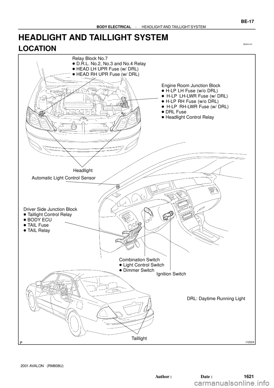
Relay Block No.7
� D.R.L. No.2, No.3 and No.4 Relay
� HEAD LH UPR Fuse (w/ DRL)
� HEAD RH UPR Fuse (w/ DRL)
Engine Room Junction Block
� H-LP LH Fuse (w/o DRL)
� H-LP LH-LWR Fuse (w/ DRL)
� H-LP RH Fuse (w/o DRL)
� H-LP RH-LWR Fuse (w/ DRL)
� DRL Fuse
� Headlight Control Relay
Headlight
Driver Side Junction Block
� Taillight Control Relay
� BODY ECU
� TAIL Fuse
� TAIL Relay
Ignition Switch
Taillight
Combination Switch
� Light Control Switch
� Dimmer Switch
Automatic Light Control Sensor
DRL: Daytime Running Light
- BODY ELECTRICALHEADLIGHT AND TAILLIGHT SYSTEM
BE-17
1621 Author�: Date�:
2001 AVALON (RM808U)
HEADLIGHT AND TAILLIGHT SYSTEM
LOCATION
Page 253 of 1897
BE0I2-03
I12527
Front Personal Light
Vanity LightInterior Light Assembly
Door Courtesy LightDoor Courtesy Switch
Door Courtesy Light
Door Courtesy Switch
Driver Side Junction Block
� DOME Fuse
� Body ECU
Rear Interior Light Assembly
Luggage Compartment Light
BE-30
- BODY ELECTRICALINTERIOR LIGHT SYSTEM
1634 Author�: Date�:
2001 AVALON (RM808U)
INTERIOR LIGHT SYSTEM
LOCATION
Page 254 of 1897
BE1DI-01
I01256
1 3
867 4
5 2
LOCKACC
START
ON
N20125
ONOFF
1 2
I05741
1 2
3 4
1
2 3
4
BE-16- BODY ELECTRICALIGNITION SWITCH AND KEY UNLOCK WARNING
SWITCH
1620 Author�: Date�:
2001 AVALON (RM808U)
INSPECTION
1. INSPECT IGNITION SWITCH CONTINUITY
Switch positionTester connectionSpecified condition
LOCK-No continuity
ACC2 - 3Continuity
ON2 - 3 - 4
6 - 7Continuity
START1 - 2 - 4
6 - 7 - 8Continuity
If continuity is not as specified, replace the switch.
2. INSPECT KEY UNLOCK WARNING SWITCH CONTI-
NUITY
ConditionTester connectionSpecified condition
Switch OFF
(Key removed) -No continuity
Switch ON
(Key set)1 - 2Continuity
If continuity is not as specified, replace the switch.
3. INSPECT IG1 RELAY CONTINUITY
ConditionTester connectionSpecified condition
Constant3 - 4Continuity
Apply B+ between
terninal 3 and 41 - 2Continuity
If continuity is not as specified, replace the switch.
Page 255 of 1897
BE0HT-04
I12523
Ignition Switch
� Key Unlock Warning Switch
Driver Side Junction Block
� ECU ACC Fuse
� ECU I/G No.2 Fuse
� IG1 Relay
� BODY ECU
- BODY ELECTRICALIGNITION SWITCH AND KEY UNLOCK WARNING
SWITCHBE-15
1619 Author�: Date�:
2001 AVALON (RM808U)
IGNITION SWITCH AND KEY UNLOCK WARNING SWITCH
LOCATION
Page 256 of 1897

INSPECTION
1. INSPECT LUGGAGE CO")
BE1EH-01
I03433
Not turned
Unlock
I13485
1
2
I13334
I04020
1
- BODY ELECTRICALLUGGAGE COMPARTMENT DOOR OPENER SYSTEM
BE-125
1729 Author�: Date�:
2001 AVALON (RM808U)
INSPECTION
1. INSPECT LUGGAGE COMPARTMENT DOOR KEY
LOCK AND UNLOCK SWITCH CONTINUITY
Switch positionTester connectionSpecified condition
Not turned-No continuity
UNLOCK1 - 2Continuity
If continuity is not as specified, replace the switch.
2. INSPECT LUGGAGE COMPARTMENT DOOR OPEN-
ER MAIN SWITCH CONTINUITY
Switch positionTester connectionSpecified condition
OFF-No continuity
ON1 - 2Continuity
If continuity is not as specified, replace the switch.
3. INSPECT LUGGAGE COMPARTMENT DOOR OPEN-
ER CANCEL SWITCH CONTINUITY
Switch positionTester connectionSpecified condition
OFF-No continuity
ON1 - 2Continuity
If continuity is not as specified, replace the switch.
4. INSPECT LUGGAGE COMPARTMENT DOOR OPEN-
ER MOTOR OPERATION
Connect positive (+) lead to the terminal 1 and negative (-) lead
to the opener motor body, and check that the motor operateds.
If operation is not as specified, replace the lock.
Page 257 of 1897
BE1EG-01
I13482
Driver Side Junction Block
� OPENER Fuse
Luggage Compartment Main Switch
Luggage Compartment Cancel Switch
Luggage Compartment Door
Unlock Motor
BE-124
- BODY ELECTRICALLUGGAGE COMPARTMENT DOOR OPENER SYSTEM
1728 Author�: Date�:
2001 AVALON (RM808U)
LUGGAGE COMPARTMENT DOOR OPENER SYSTEM
LOCATION
Page 258 of 1897
 To disable auto door lock:
(1) Enter the vehicle and shut")
BE212-01
BE-88
- BODY ELECTRICALPOWER DOOR LOCK CONTROL SYSTEM
1692 Author�: Date�:
ADJUSTMENT
ENABLING/DISABLING AUTO DOOR LOCK FUNCTION
(a) To disable auto door lock:
(1) Enter the vehicle and shut all doors.
(2) Insert the key into the ignition cylinder and turn it to
the ON position (not ACC).
(3) Open the driver's door and keep it open.
(4) Turn the key to the LOCK position and remove it
from the ignition cylinder.
(5) Insert the key into the ignition cylinder and remove
it. Repeat this operation three more times. (End this
step with the key out of the ignition cylinder.)
(6) Push the ºUNLOCKº button on the driver's door
master switch 5 times within 10 seconds. Wait at
least 10 seconds and shut the driver's door.
(7) Verify auto lock operation has been disabled by
starting the engine, putting the vehicle into a gear
and releasing the brake pedal.
(b) To enable auto door lock:
Follow the same sequence as above, except step 6. In step 6,
push the ºLOCKº button on the driver's door master switch 5
times within 10 seconds. Wait at least 10 seconds and shut the
driver 's door.