Page 286 of 1897
BE0IR-03
I12538
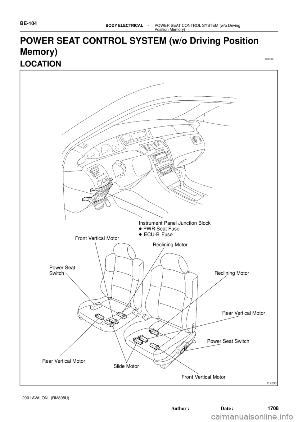
Instrument Panel Junction Block
� PWR Seat Fuse
� ECU-B Fuse
Reclining Motor Front Vertical Motor
Power Seat
Switch
Rear Vertical Motor
Reclining Motor
Power Seat SwitchRear Vertical Motor
Slide Motor
Front Vertical Motor BE-104
- BODY ELECTRICALPOWER SEAT CONTROL SYSTEM (w/o Driving
Position Memory)
1708 Author�: Date�:
2001 AVALON (RM808U)
POWER SEAT CONTROL SYSTEM (w/o Driving Position
Memory)
LOCATION
Page 289 of 1897

4. INSPECT POWER MAIN RELAY CONTINUITY
C")
I01200
2 1
35
2 5
1 3
I12547
2
1
I12548
21
I12549
1
2
I12550
1
2
BE-74
- BODY ELECTRICALPOWER WINDOW CONTROL SYSTEM
1678 Author�: Date�:
2001 AVALON (RM808U)
4. INSPECT POWER MAIN RELAY CONTINUITY
ConditionTester connectionSpecified condition
Constant1 - 2Continuity
Apply B+ between
terminals 1 and 2.3 - 5Continuity
If continuity is not as specified, replace the relay.
5. Driver 's Door:
INSPECT POWER WINDOW MOTOR OPERATION
(a) Connect the positive (+) lead from the battery to terminal
1 and the negative (-) lead to terminal 2, and check that
the motor turns clockwise.
(b) Reverse the polarity, check that the motor turns counter-
clockwise.
If operation is not as specified, replace the motor.
NOTICE:
Since the jam protection may not work properly be sure to
conduct procedures described in ºHOW TO RESET POW-
ER MOTOR (RESET AND PULSE SWITCH)º after this in-
spection.
6. Front Passenger's Door:
INSPECT POWER WINDOW MOTOR OPERATION
(a) Connect the positive (+) lead from the battery to terminal
2 and the negative (-) lead to terminal 1, and check that
the motor turns clockwise.
(b) Reverse the polarity, check that the motor turns counter-
clockwise.
If operation is not as specified, replace the motor.
Page 290 of 1897

7. Rear Left Side Door:
INSPECT POWER WINDOW MOTOR")
I12553
1
2
I12554
1
2
I12551
2
1
I12552
21
I12555
1
2
- BODY ELECTRICALPOWER WINDOW CONTROL SYSTEM
BE-75
1679 Author�: Date�:
2001 AVALON (RM808U)
7. Rear Left Side Door:
INSPECT POWER WINDOW MOTOR OPERATION
(a) Connect the positive (+) lead from the battery to terminal
2 and the negative (-) lead to terminal 1, and check that
the motor turns clockwise.
(b) Reverse the polarity, check that the motor turns counter-
clockwise.
If operation is not as specified, replace the motor.
8. Rear Right Side Door:
INSPECT POWER WINDOW MOTOR OPERATION
(a) Connect the positive (+) lead from the battery to terminal
1 and the negative (-) lead to terminal 2, and check that
the motor turns clockwise.
(b) Reverse the polarity, check that the motor turns counter-
clockwise.
If operation is not as specified, replace the motor.
9. Driver 's door:
INSPECT POWER WINDOW MOTOR PTC THERM-
ISTOR OPERATION
(a) Disconnect the connector from the power window motor.
(b) Connect the positive (+) lead from the ammeter to termi-
nal 2 on the wire harness side connector and the negative
(-) lead to negative terminal of the battery.
(c) Connect the positive (+) lead from the battery to terminal
1 on the wire harness side connector, and raise the win-
dow to the fully position.
Page 295 of 1897
BE0IH-03
I12534
Driver Side Junction Block
� FL P/W, FR P/W, RL P/W, RR P/W Fuse
� Power Main Relay
� Body ECU
Front Power Window MotorIgnition SwitchPower Window Switch
(Passenger Door ECU)
Rear Power Window Motor
Power Window Master Switch
(Driver Door ECU)
Rear Power Window Switch
BE-72
- BODY ELECTRICALPOWER WINDOW CONTROL SYSTEM
1676 Author�: Date�:
2001 AVALON (RM808U)
LOCATION
Page 300 of 1897
BE0IV-05
I13483
Instrument Panel Junction Block
� SEAT HTR Fuse
� Ignition Main Relay
Seat Heater
� Seat Cushion
Seat Heater
� Seat BackIgnition SwitchHeater Control Panel
� Seat Heater Switch
- BODY ELECTRICALSEAT HEATER SYSTEM
BE-121
1725 Author�: Date�:
2001 AVALON (RM808U)
SEAT HEATER SYSTEM
LOCATION
Page 302 of 1897
BE0I6-05
I12529
Stop Light Switch
Driver Side Junction Block
� STOP Fuse
Light Failure Sensor
Stop Light
HI-Mounted Stop Light
- BODY ELECTRICALSTOP LIGHT SYSTEM
BE-35
1639 Author�: Date�:
2001 AVALON (RM808U)
STOP LIGHT SYSTEM
LOCATION
Page 303 of 1897

INSPECTION
1. INSPECT SLIDING ROOF CONTROL SWITCH CONTI-
NUITY
Switch positio")
BE1E2-01
I04045
Wire Harness Side:
- BODY ELECTRICALSLIDING ROOF SYSTEM
BE-103
1707 Author�: Date�:
2001 AVALON (RM808U)
INSPECTION
1. INSPECT SLIDING ROOF CONTROL SWITCH CONTI-
NUITY
Switch positionTester connectionSpecified condition
Slide Open2 - 3Continuity
Tilt Up1 - 2Continuity
If continuity is not as specified, replace the switch.
2. INSPECT SLIDING ROOF CONTROL ASSEMBLY CIR-
CUIT
Disconnect the connector from the assembly and inspect the
connector on the wire harness side, as shown in the chart.
Tester connectionConditionSpecified condition
3 - Ground
Driver's door courtesy switch ºONº
(Door opened)Continuity3 Ground
(DCTY)Driver's door courtesy switch ºOFFº
(Door closed)No continuity
4 - Ground
Passenger's door courtesy switch ºONº
(Door opened)Continuity4 Ground
(PCTY)Passenger's door courtesy switch ºOFFº
(Door closed)No continuity
5 - Ground
(+B)ConstantBattery positive voltage
7 - Ground
(E)ConstantContinuity
8 - GroundIgnition switch LOCK or ACCNo voltage8 Ground
(IG)Ignition switch ONBattery positive voltage
9 - Ground
(DOWN)Sliding roof control switch OPEN / DOWNContinuity
9 - Ground
(DOWN)Sliding roof control switch CLOSE / UPNo continuity
10 - GroundSliding roof control switch CLOSE / UPContinuity10 Ground
(UP)Sliding roof control switch OPEN / DOWNNo continuity
*: Exceptions: During 60 second period after ignition switch ON
" OFF (ACC) or until driver of passenger door in opened after
ignition switch ON " OFF (ACC).
If circuit is as specified, replace the assembly.
Page 304 of 1897
BE0IP-06
I12542
Instrument Panel Junction Block
� Sun Roof Fuse
� GAUGE No,1 FuseIgnition Switch Sliding Roof Assembly
� Sliding Roof Switch
� Sliding Roof Control ECU
Door Courtesy Switch
BE-102
- BODY ELECTRICALSLIDING ROOF SYSTEM
1706 Author�: Date�:
2001 AVALON (RM808U)
LOCATION