Page 1848 of 1897

HINT:
At the time of installation, please refer to the following items.
�Coat gear oil to the inboard jo")
W03144
- SUSPENSION AND AXLEFRONT DRIVE SHAFT
SA-17
1351 Author�: Date�:
2001 AVALON (RM808U)
HINT:
At the time of installation, please refer to the following items.
�Coat gear oil to the inboard joint shaft and differential
case sliding surface.
�Before installing the drive shaft, set the snap ring opening
side facing downward.
�Whether or not the inboard joint shaft is making contact
with the pinion shaft can be known by the sound or feeling
when driving it in.
�After installation, check that there is 2 - 3 mm (0.08 - 0.12
in.) of play in the axial direction.
�After installation, check that the drive shaft cannot be re-
moved by hand.
(b) Using a screwdriver, remove the snap ring from the in-
board joint shaft.
9. RH drive shaft:
REMOVE DRIVE SHAFT
(a) Remove the bearing lock bolt.
Torque: 32 N´m (330 kgf´cm, 24 ft´lbf)
(b) Using pliers, remove the snap ring and drive shaft.
NOTICE:
Be careful not to damage the dust cover and oil seal.
HINT:
At the time of installation, coat gear oil to the inboard joint shaft
and differential case sliding surface.
Page 1849 of 1897
SA0VA-02
F06451
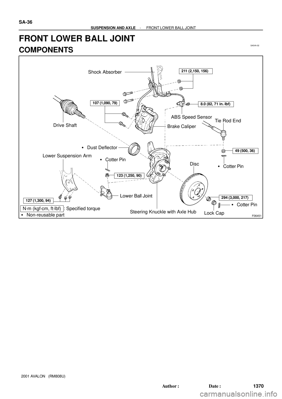
N´m (kgf´cm, ft´lbf) : Specified torque
� Non-reusable part
Shock Absorber211 (2,150, 156)
8.0 (82, 71 in.´lbf)
ABS Speed Sensor
Brake Caliper
49 (500, 36)
� Cotter PinDisc
� Cotter Pin
Steering Knuckle with Axle Hub
Lower Ball Joint
123 (1,250, 90)
� Cotter Pin
127 (1,300, 94)
Lower Suspension Arm
� Dust Deflector
Drive ShaftTie Rod End
Lock Cap
107 (1,090, 79)
294 (3,000, 217)
SA-36
- SUSPENSION AND AXLEFRONT LOWER BALL JOINT
1370 Author�: Date�:
2001 AVALON (RM808U)
FRONT LOWER BALL JOINT
COMPONENTS
Page 1870 of 1897

5. INSPECT TOE-IN
Toe-in:
Toe-in")
SA3213
Front A
DB
C
F02245
F02246
SA0028
Front AB
A B
A: Inside
B: Outside SA-6
- SUSPENSION AND AXLEFRONT WHEEL ALIGNMENT
1340 Author�: Date�:
2001 AVALON (RM808U)
5. INSPECT TOE-IN
Toe-in:
Toe-in
(total)A + B: 0° ± 12' (0° ± 0.2°)
C - D: 0 ± 2 mm (0 ± 0.08 in.)
If the toe-in is not within the specified value, adjust it at the rack
ends.
6. ADJUST TOE-IN
(a) Remove the rack boot set clips.
(b) Loosen the tie rod end lock nuts.
(c) Turn the right and left rack ends by an equal amount to
adjust the toe-in.
HINT:
Try to adjust the toe-in to the center of the specified value.
(d) Make sure that the lengths of the right and left rack ends
are the same.
Rack end length difference: 1.5 mm (0.059 in.) or less
(e) Torque the tie rod end lock nuts.
Torque: 74 N´m (750 kgf´cm, 54 ft´lbf)
(f) Place the boots on the seats and install the clips.
HINT:
Make sure that the boots are not twisted.
7. INSPECT WHEEL ANGLE
Turn the steering wheel fully, and measure the turning angle.
Wheel turning angle:
Inside wheel35°45' ± 1° (35.75° ± 1°)
Outside wheel: Reference31°23' (31.38°)
If the right and left inside wheel angles differ from the specified
value, check the right and left rack end lengths.
Page 1877 of 1897
SA1F8-02
F06459
F06461
- SUSPENSION AND AXLEREAR LOWER SUSPENSION ARM AND STRUT ROD
SA-59
1393 Author�: Date�:
2001 AVALON (RM808U)
DISASSEMBLY
DISASSEMBLE NO. 2 LOWER SUSPENSION ARM
(a) Loosen the 2 lock nuts.
(b) Turn the adjusting tube and disassemble the No. 2 lower
suspension arm.
(c) Remove the 2 lock nuts.
Page 1879 of 1897
SA1F9-02
F06460
W03223
AB
F06462
SA-60
- SUSPENSION AND AXLEREAR LOWER SUSPENSION ARM AND STRUT ROD
1394 Author�: Date�:
2001 AVALON (RM808U)
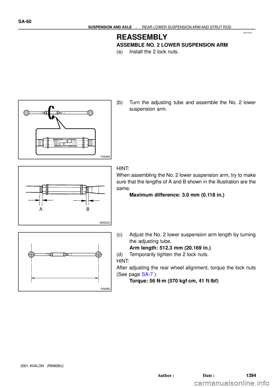
REASSEMBLY
ASSEMBLE NO. 2 LOWER SUSPENSION ARM
(a) Install the 2 lock nuts.
(b) Turn the adjusting tube and assemble the No. 2 lower
suspension arm.
HINT:
When assembling the No. 2 lower suspension arm, try to make
sure that the lengths of A and B shown in the illustration are the
same.
Maximum difference: 3.0 mm (0.118 in.)
(c) Adjust the No. 2 lower suspension arm length by turning
the adjusting tube.
Arm length: 512.3 mm (20.169 in.)
(d) Temporarily tighten the 2 lock nuts.
HINT:
After adjusting the rear wheel alignment, torque the lock nuts
(See page SA-7).
Torque: 56 N´m (570 kgf´cm, 41 ft´lbf)
Page 1893 of 1897

REAR WHEEL ALIGNMENT
INSPECTION
1. MEASURE VEHICLE HEIGHT (See pag")
SA1DQ-03
SA3213
Front A
DB
C
F04051
F04052
- SUSPENSION AND AXLEREAR WHEEL ALIGNMENT
SA-7
1341 Author�: Date�:
2001 AVALON (RM808U)
REAR WHEEL ALIGNMENT
INSPECTION
1. MEASURE VEHICLE HEIGHT (See page SA-4)
2. INSTALL CAMBER-CASTER-KINGPIN GAUGE OR
POSITION VEHICLE ON WHEEL ALIGNMENT TES-
TER
Follow the specific instructions of the equipment manufacturer.
3. INSPECT CAMBER
Camber:
Camber
Right-left error-0°43' ± 45' (-0.72° ± 0.75°)
45' (0.75°) or less
If the measured value is not within the specified value, inspect
the suspension parts for damage and/or wear and replace them
if necessary because camber is not adjustable.
4. INSPECT TOE-IN
Toe-in:
Toe-in
(total)A + B: 0°24' ± 12' (0.4° ± 0.2°)
C - D: 4 ± 2 mm (0.16 ± 0.08 in.)
If the toe-in is not within the specified value, adjust it at the
No. 2 lower suspension arm.
5. ADJUST TOE-IN
(a) Measure the lengths of the right and left No. 2 lower sus-
pension arms.
No. 2 lower suspension arm length difference:
1 mm (0.04 in.) or less
If the right-left difference is greater than the specified value, ad-
just the length.
(b) Loosen the lock nuts.
(c) Turn the right and left adjusting tube by an equal amount
to adjust toe-in.
HINT:
�Try to adjust the toe-in to the center value.
�One turn of the each adjusting tube will adjust the toe-in
by about 36' (0.6°, 6.7 mm, 0.264 in.).
(d) Torque the lock nuts.
Torque: 56 N´m (570 kgf´cm, 41 ft´lbf)