Page 1826 of 1897

15. INSTALL LOWER NO. 1 INSTRUMENT PANEL SUB-
ASSEMBLY
(a) Connect the connec")
F03856Marks
F08828
Torx ScrewScrew Case
SR-24
- STEERINGTILT STEERING COLUMN
1487 Author�: Date�:
2001 AVALON (RM808U)
15. INSTALL LOWER NO. 1 INSTRUMENT PANEL SUB-
ASSEMBLY
(a) Connect the connectors and install the lower No. 1 instru-
ment panel sub-assembly.
(b) Install the 2 screws.
(c) Connect the hood lock release lever with the 2 screws.
16. CENTER SPIRAL CABLE
(a) Check that the front wheels are facing straight ahead.
(b) Turn the spiral cable counterclockwise by hand until it be-
comes harder to turn.
(c) Then rotate the spiral cable clockwise about 2.5 turns to
align the marks.
HINT:
The spiral cable will rotate about 2.5 turns to either left or right
of the center.
17. INSTALL STEERING WHEEL
(a) Align the matchmarks on the steering wheel and main
shaft assembly.
(b) Install the steering wheel set nut.
Torque: 50 N´m (510 kgf´cm, 37 ft´lbf)
(c) Connect the connector.
18. INSTALL STEERING WHEEL PAD
NOTICE:
�Never use airbag parts from another vehicle. When
replacing parts, replace with new ones.
�Make sure the wheel pad is installed to the specified
torque.
�If the wheel pad has been dropped, or there are
cracks, dents or other defects on the case or connec-
tor, replace the wheel pad with a new one.
�When installing the wheel pad, take care that the wir-
ings do not interfere with other parts and are not
pinched between other parts.
(a) Connect the airbag connector.
(b) Install the steering wheel pad after confirming that the cir-
cumference groove of the torx screws is caught on the
screw case.
(c) Using a torx socket wrench, install the 2 screws.
Torque: 8.8 N´m (90 kgf´cm, 78 in.´lbf)
(d) Install the 2 steering wheel lower No. 2 covers.
19. CHECK STEERING WHEEL CENTER POINT
20. w/ VSC:
PERFORM STEERING ANGLE SENSOR ZERO POINT
CALIBRATION (See page DI-252)
Page 1827 of 1897

REASSEMBLY
NOTICE:
When using a vise,")
SR0Z7-01
F09910
SST
No. 2 Steering
Column Ring
F09917Tilt Spring and Spring Guide
SR-20
- STEERINGTILT STEERING COLUMN
1483 Author�: Date�:
2001 AVALON (RM808U)
REASSEMBLY
NOTICE:
When using a vise, do not overtighten it.
1. COAT PARTS INDICATED BY ARROWS WITH MOLYB-
DENUM DISULFIDE LITHIUM BASE GREASE
(See page SR-9)
2. INSTALL TILT LEVER
Install the tilt lever with a new tilt lever lock shaft.
Torque: 9.0 N´m (90 kgf´cm, 78 in.´lbf)
3. INSTALL MAIN SHAFT ASSEMBLY
(a) Install the main shaft collar, main shaft bushing, compres-
sion spring and spring retainer.
(b) Install a new No. 2 steering column ring to the main shaft
assembly.
(c) Install SST to the main shaft assembly, as shown in the
illustration.
SST 09612-07010
(d) Using SST, push down the No. 2 steering column ring until
it fits into the shaft groove and install the main shaft as-
sembly.
NOTICE:
Do not bend the universal joint of the shaft assembly more
than 20°.
HINT:
Hold the main shaft assembly with your hand so that it does not
rotate.
4. INSTALL STEERING COLUMN UPPER TUBE WITH
MAIN SHAFT ASSEMBLY
(a) Install the steering column upper tube with the main shaft
assembly into the column tube assembly.
(b) Install the tilt spring and spring guide.
(c) Using a vise to hold the steering column upper tube.
(d) Temporarily install 2 new No. 2 tilt steering bolts.
Page 1828 of 1897

(e) Using a punch and a hammer, tap in the No. 2 tilt steering
bolt.
(f) Using a pin punc")
F09918Pin Punch
F09919
F08833
- STEERINGTILT STEERING COLUMN
SR-21
1484 Author�: Date�:
2001 AVALON (RM808U)
(e) Using a punch and a hammer, tap in the No. 2 tilt steering
bolt.
(f) Using a pin punch, stake on 3 places evenly around the
hole as shown in the illustration.
5. INSTALL TURN SIGNAL BRACKET
(a) Install the turn signal bracket with 2 new torx screws.
Torque: 7.5 N´m (75 kgf´cm, 65 in.´lbf)
HINT:
Set the hole of the turn signal bracket and projection of steering
column upper tube.
(b) Install the tension spring.
6. Column shift:
INSTALL SHIFT LEVER HOUSING
(a) Install the shift lever housing with 3 new torx screws.
Torque: 10 N´m (100 kgf´cm, 7 ft´lbf)
(b) Install the shift lever with a new torx screw.
Torque: 11 N´m (110 kgf´cm, 8 ft´lbf)
(c) Install the shift lock solenoid bracket with 2 new torx
screws.
Torque: 3.4 N´m (35 kgf´cm, 30 in.´lbf)
(d) Install the shift lock switch with a new torx screw.
Torque: 2.8 N´m (29 kgf´cm, 25 in.´lbf)
7. INSTALL COLUMN UPPER BRACKET
(a) Install the column upper bracket with 2 new tapered-
head bolts.
(b) Tighten the tapered-head bolts until the bolt heads break
off.
8. Column shift:
INSTALL SHIFT LOCK CONTROL ECU
Install the shift lock control ECU and connect the 3 connectors.
9. INSTALL KEY CYLINDER LAMP ASSEMBLY
Install the key cylinder lamp assembly with screw.
10. w/ Engine immobiliser system:
INSTALL TRANSPONDER KEY COIL
Page 1830 of 1897

3. REMOVE LOWER NO. 1 INSTRUMENT PANEL SUB-
ASSEMBLY
(a) Remove the 2 screws and disconnect the hood lock re-
l")
F08830
- STEERINGTILT STEERING COLUMN
SR-13
1476 Author�: Date�:
2001 AVALON (RM808U)
3. REMOVE LOWER NO. 1 INSTRUMENT PANEL SUB-
ASSEMBLY
(a) Remove the 2 screws and disconnect the hood lock re-
lease lever.
(b) Remove the 2 screws.
(c) Disconnect the connectors and remove the lower No. 1
instrument panel sub-assembly.
4. REMOVE LOWER LH INSTRUMENT PANEL INSERT
SUB-ASSEMBL Y
(a) Disconnect the connectors.
(b) Remove the 4 bolts and lower LH instrument panel insert
sub-assembly .
5. REMOVE NO. 2 HEATER TO REGISTER DUCT
Remove the clip and No. 2 heater to register duct.
6. REMOVE NO. 2 COLUMN LOWER COVER, COLUMN
UPPER AND LOWER COVERS
(a) Remove the No. 2 column lower cover.
(b) Remove the 3 screws, column upper and lower covers.
7. REMOVE COMBINATION SWITCH WITH SPIRAL
CABLE
(a) Disconnect the connectors.
(b) Disconnect the airbag connector.
(c) Remove the 3 screws and combination switch with spiral
cable.
8. REMOVE SPIRAL CABLE (See page BE-18)
NOTICE:
Do not disassemble the spiral cable or apply oil to it.
9. REMOVE LOWER INSTRUMENT FINISH PANEL AS-
SEMBLY
10. REMOVE AIR CLEANER ASSEMBLY WITH AIR
CLEANER HOSE
(a) Loosen the hose clamps.
(b) Disconnect the connectors.
(c) Remove the 3 bolts and air cleaner assembly with air
cleaner hose.
11. DISCONNECT INTERMEDIATE SHAFT SUB- AS-
SEMBLY
(a) Loosen the clamp and disconnect the No. 2 column hole
cover sub-assembly.
Page 1833 of 1897
SA0VR-02
F04047Non-reusable part �
N´m (kgf´cm, ft´lbf) : Specified torque
Shock Absorber
Drive Shaft
Hub BoltTie Rod End
ABS Speed Sensor
Brake Caliper
� Cotter Pin
Lower Suspension Arm
� Cotter Pin � Bearing � Snap Ring � Dust Deflector� Cotter Pin
Lock Cap
Disc
Axle Hub Lower Ball JointDust Cover Steering Knuckle
211 (2,150, 156)
107 (1,090, 79)
49 (500, 36)
8.0 (82, 71 in.´lbf)
294 (3,000, 217)
127 (1,300, 94)
123 (1,250, 90)
8.3 (85, 74 in.´lbf)
SA-8
- SUSPENSION AND AXLEFRONT AXLE HUB
1342 Author�: Date�:
2001 AVALON (RM808U)
FRONT AXLE HUB
COMPONENTS
Page 1837 of 1897

REMOVAL
1. REMOVE FRONT WHEEL
Torque: 103 N´m (1,050 kgf´cm, 76 ft´lbf)
2. CHECK")
SA0VS-02
W03084
W03093
W03139
- SUSPENSION AND AXLEFRONT AXLE HUB
SA-9
1343 Author�: Date�:
2001 AVALON (RM808U)
REMOVAL
1. REMOVE FRONT WHEEL
Torque: 103 N´m (1,050 kgf´cm, 76 ft´lbf)
2. CHECK BEARING BACKLASH AND AXLE HUB DEVI-
ATION
(a) Remove the 2 bolts, brake caliper and disc.
(b) Support the brake caliper securely.
(c) Using a dial indicator, check the backlash near the center
of the axle hub.
Maximum: 0.05 mm (0.0020 in.)
If the backlash exceeds the maximum, replace the bearing.
(d) Using a dial indicator, check the deviation at the surface
of the axle hub outside the hub bolt.
Maximum: 0.05 mm (0.0020 in.)
If the deviation exceeds the maximum, replace the axle hub.
(e) Install the disc, brake caliper and 2 bolts.
Torque: 107 N´m (1,090 kgf´cm, 79 ft´lbf)
3. REMOVE DRIVE SHAFT LOCK NUT
(a) Remove the cotter pin and lock cap.
(b) While applying the brakes, remove the nut.
Torque: 294 N´m (3,000 kgf´cm, 217 ft´lbf)
(c) Remove the 2 bolts, brake caliper and disc.
(d) Support the brake caliper securely.
4. DISCONNECT ABS SPEED SENSOR AND WIRE HAR-
NESS CLAMP
Remove the bolt and disconnect the ABS speed sensor and
wire harness clamp.
Torque: 8.0 N´m (82 kgf´cm, 71 in.´lbf)
5. LOOSEN 2 NUTS ON LOWER SIDE OF SHOCK AB-
SORBER
HINT:
Do not remove the bolts.
Torque: 211 N´m (2,150 kgf´cm, 156 ft´lbf)
HINT:
At the this time of installation, coat the nut's thread with engine
oil.
Page 1839 of 1897
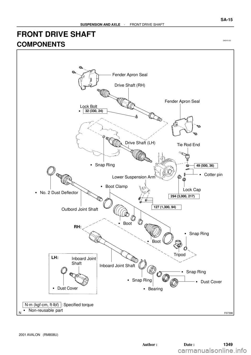
SA0VX-02
F07396
Fender Apron Seal
Drive Shaft (RH)
32 (330, 24)�Lock Bolt
� Snap Ring
� No. 2 Dust Deflector
Outbord Joint Shaft
Fender Apron Seal
Tie Rod End
49 (500, 36)
� Cotter pin
Lock Cap
294 (3,000, 217)
Lower Suspension Arm
127 (1,300, 94)
� Boot Clamp
� Boot
� Boot
� Snap Ring
Tripod RH:
Inboard Joint Shaft
� Snap Ring
� Bearing
� Snap Ring
� Dust Cover LH:
Inboard Joint
Shaft
� Dust Cover
N´m (kgf´cm, ft´lbf) : Specified torque
� Non-reusable part
Drive Shaft (LH)
- SUSPENSION AND AXLEFRONT DRIVE SHAFT
SA-15
1349 Author�: Date�:
2001 AVALON (RM808U)
FRONT DRIVE SHAFT
COMPONENTS
Page 1847 of 1897

REMOVAL
NOTICE:
�The hub bearing could be damaged if it is subjected
t")
SA0VY-02
FA1535
SST
W03093
W03142
F07389
SA-16
- SUSPENSION AND AXLEFRONT DRIVE SHAFT
1350 Author�: Date�:
2001 AVALON (RM808U)
REMOVAL
NOTICE:
�The hub bearing could be damaged if it is subjected
to the vehicle weight, such as when moving the ve-
hicle with the drive shaft removed.
Therefore, if it is absolutely necessary to place the ve-
hicle weight on the hub bearing, first support it with
SST.
SST 09608-16042 (09608-02021, 09608-02041)
�After disconnecting the drive shaft from the axle hub,
work carefully so as not to damage the ABS speed
sensor rotor serration on the drive shaft.
1. REMOVE FRONT WHEEL
Torque: 103 N´m (1,050 kgf´cm, 76 ft´lbf)
2. REMOVE FRONT FENDER APRON SEAL
3. DRAIN ATF
4. REMOVE DRIVE SHAFT LOCK NUT
(a) Remove the cotter pin and lock cap.
(b) While applying brakes, remove the nut.
Torque: 294 N´m (3,000 kgf´cm, 217 ft´lbf)
5. DISCONNECT TIE ROD END FROM STEERING
KNUCKLE (See page SA-9)
6. DISCONNECT LOWER SUSPENSION ARM FROM
LOWER BALL JOINT (See page SA-9)
7. DISCONNECT DRIVE SHAFT FROM AXLE HUB
Using a plastic hammer, disconnect the drive shaft from the axle
hub.
NOTICE:
Be careful not to damage the boot and ABS speed sensor
rotor.
8. LH drive shaft:
REMOVE DRIVE SHAFT
(a) Using a hub nut wrench and hammer handle or an equiva-
lent, remove the drive shaft.
NOTICE:
Be careful not to damage the dust cover and oil seal.