Page 1780 of 1897
Z15499
Oil
Reservoir
PS Vane
Pump PS Gear
SST Open
Z15500
Oil
Reservoir
PS Vane
Pump PS Gear
SST Open Lock Position
- STEERINGPOWER STEERING FLUID
SR-7
1470 Author�: Date�:
2001 AVALON (RM808U)
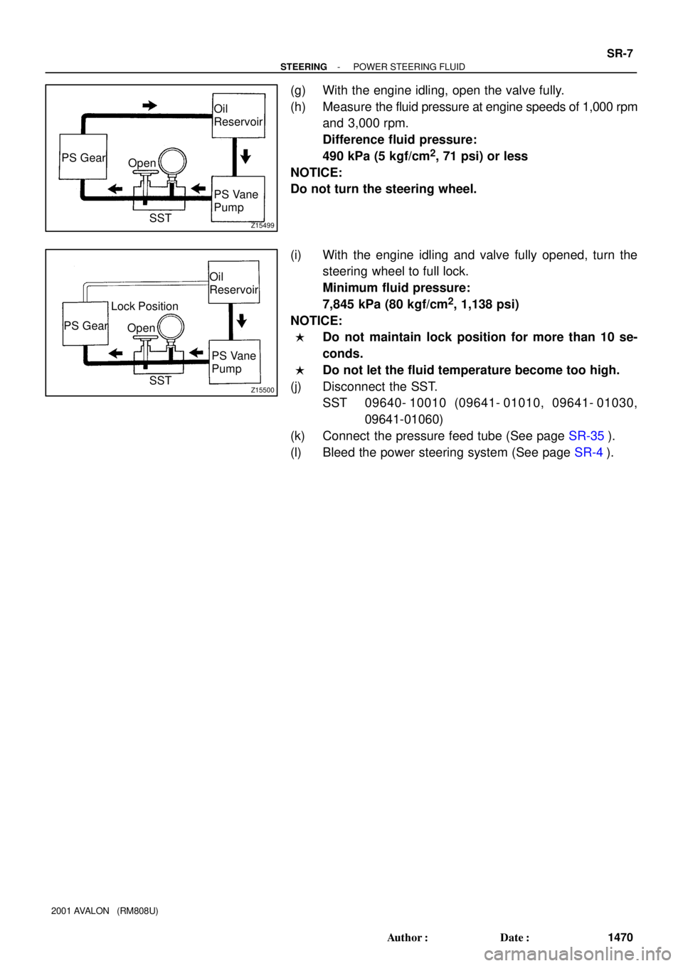
(g) With the engine idling, open the valve fully.
(h) Measure the fluid pressure at engine speeds of 1,000 rpm
and 3,000 rpm.
Difference fluid pressure:
490 kPa (5 kgf/cm
2, 71 psi) or less
NOTICE:
Do not turn the steering wheel.
(i) With the engine idling and valve fully opened, turn the
steering wheel to full lock.
Minimum fluid pressure:
7,845 kPa (80 kgf/cm
2, 1,138 psi)
NOTICE:
�Do not maintain lock position for more than 10 se-
conds.
�Do not let the fluid temperature become too high.
(j) Disconnect the SST.
SST 09640- 10010 (09641- 01010, 09641- 01030,
09641-01060)
(k) Connect the pressure feed tube (See page SR-35).
(l) Bleed the power steering system (See page SR-4).
Page 1782 of 1897
Z19562
� O-Ring
* For use with SST � Non-reusable partRack Housing
No. 2 Grommet
Rack HousingRack Boot
Clip
Tie Rod End
Lock Nut
Rack End
Steering Rack Rack Housing
No. 2 Bracket� Clamp
� Claw Washer
� Teflon Ring
� Oil Seal
� Wire
� Oil Seal
Molybdenum disulfide lithium base grease
Power steering fluidCylinder End Stopper
Bushing � Claw Washer Rack End
83 (850, 61)
*60 (610, 44)
� Clamp Rack Boot Clip
Lock Nut Tie Rod End
74 (750, 54)
74 (750, 54)
N´m (kgf´cm, ft´lbf) : Specified torque
� O-Ring
83 (850, 61)
*60 (610, 44)
SR-38
- STEERINGPOWER STEERING GEAR
1501 Author�: Date�:
2001 AVALON (RM808U)
Page 1783 of 1897
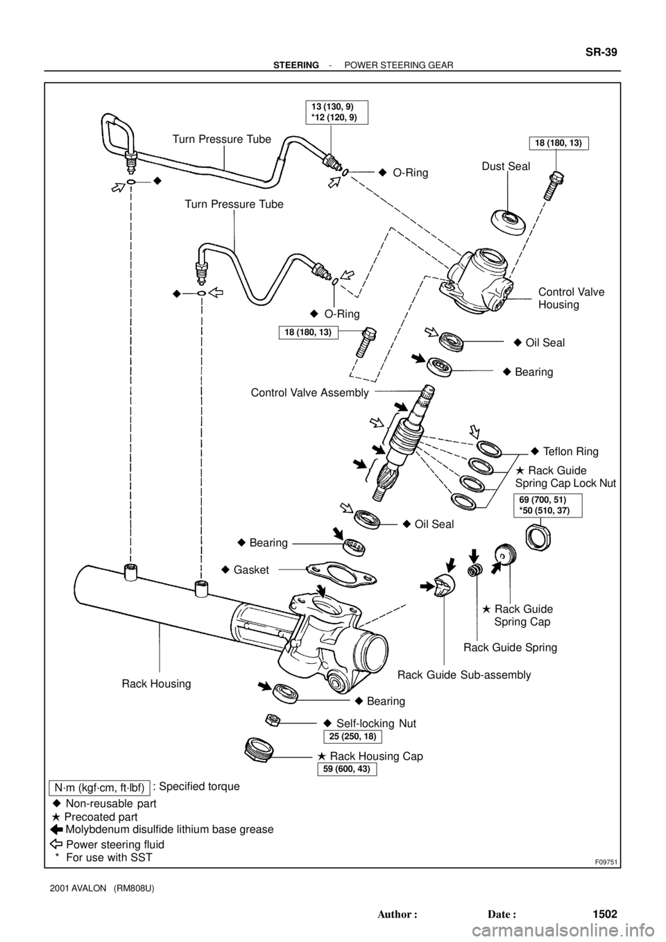
F09751
� Non-reusable part� Oil Seal � O-Ring
Molybdenum disulfide lithium base grease
Power steering fluid � Precoated part� O-Ring Turn Pressure Tube
Dust Seal
�
Control Valve AssemblyControl Valve
Housing Turn Pressure Tube
�
� Oil Seal
� Bearing
� Teflon Ring
� Bearing
� Gasket
Rack Guide Spring
Rack Guide Sub-assembly
Rack Housing
� Bearing� Rack Guide
Spring Cap Lock Nut
� Rack Guide
Spring Cap
� Self-locking Nut
� Rack Housing Cap
13 (130, 9)
*12 (120, 9)
18 (180, 13)
18 (180, 13)
69 (700, 51)
*50 (510, 37)
25 (250, 18)
59 (600, 43)
N´m (kgf´cm, ft´lbf): Specified torque
* For use with SST
- STEERINGPOWER STEERING GEAR
SR-39
1502 Author�: Date�:
2001 AVALON (RM808U)
Page 1784 of 1897

DISASSEMBLY
NOTICE:
When using a vise, do not")
SR0EV-05
W04228
SST
F13587
SST
R00429
Matchmarks
W04230
R11644
Claw Washer
- STEERINGPOWER STEERING GEAR
SR-41
1504 Author�: Date�:
2001 AVALON (RM808U)
DISASSEMBLY
NOTICE:
When using a vise, do not overtighten it.
1. SECURE PS GEAR ASSEMBLY IN VISE
Using SST, secure the PS gear assembly in a vise.
SST 09612-00012
2. REMOVE 2 TURN PRESSURE TUBES
(a) Using SST, remove the 2 turn pressure tubes.
SST 09023-38200
(b) Remove the 4 O-rings from the 2 turn pressure tubes.
3. REMOVE RH AND LH TIE ROD ENDS AND LOCK
NUTS
(a) Place matchmarks on the tie rod end and rack end.
(b) Loosen the lock nut, and remove the tie rod end and lock
nut.
(c) Employ the same manner described above to the other
side.
4. REMOVE RH AND LH CLIPS, RACK BOOTS AND
CLAMPS
(a) Using a screwdriver, loosen the clamp.
NOTICE:
Be careful not to damage the rack boot.
(b) Remove the clip and rack boot.
(c) Employ the same manner described above to the other
side.
HINT:
Mark the RH and LH rack boot.
5. REMOVE RH AND LH RACK ENDS AND CLAW WASH-
ERS
(a) Using a screwdriver and hammer, unstake the claw wash-
er.
NOTICE:
Avoid any impact on the steering rack.
Page 1785 of 1897

(b) Using a spanner (24")
R11645
SST
R11646
SSTRack Guide
Spring Cap Lock Nut
R11647
SST Rack Guide
Spring Cap
R11648
SST SR-42
- STEERINGPOWER STEERING GEAR
1505 Author�: Date�:
2001 AVALON (RM808U)
(b) Using a spanner (24 mm) hold the steering rack steadily
and using SST, remove the rack end.
SST 09922-10010
NOTICE:
Use SST 09922-10010 in the direction shown in the illustra-
tion.
(c) Remove the claw washer.
(d) Employ the same manner described above to the other
side.
HINT:
Mark the RH and LH rack ends.
6. REMOVE RACK GUIDE SPRING CAP LOCK NUT
Using SST, remove the rack guide spring cap lock nut.
SST 09922-10010
NOTICE:
Use SST 09922-10010 in the direction shown in the illustra-
tion.
7. REMOVE RACK GUIDE SPRING CAP, RACK GUIDE
SPRING, RACK GUIDE SUB-ASSEMBLY
(a) Using SST, remove the rack guide spring cap.
SST 09631-10021
(b) Remove the rack guide spring and rack guide sub-as-
sembly.
8. REMOVE RACK HOUSING CAP
9. REMOVE SELF-LOCKING NUT
Using SST, stop the control valve shaft rotating and remove the
self-locking nut.
SST 09616-0001 1
10. REMOVE DUST SEAL
Page 1786 of 1897

11. REMOV")
R11553
Matchmarks
R11554
Vinyl TapePress
Shop Rag
R11649
Matchmarks
R11650
R11651
SSTWire
Cylinder End
Stopper
- STEERINGPOWER STEERING GEAR
SR-43
1506 Author�: Date�:
2001 AVALON (RM808U)
11. REMOVE CONTROL VALVE HOUSING WITH CON-
TROL VALVE ASSEMBLY
(a) Place matchmarks on the control valve housing and rack
housing.
(b) Remove the 2 bolts and control valve housing.
(c) Remove the gasket from the rack housing.
12. REMOVE CONTROL VALVE ASSEMBLY
(a) To prevent oil seal lip damage, wind vinyl tape on the ser-
rated part of the control valve shaft.
(b) Press out the control valve assembly with the oil seal.
NOTICE:
�Place a shop rag between the valve housing and the
blocks.
�Be careful not to drop the valve assembly.
�Be careful not to damage the oil seal lip.
13. REMOVE OIL SEAL
Remove the oil seal from the control valve assembly.
14. REMOVE RACK HOUSING NO. 2 BRACKET AND
RACK HOUSING NO. 2 GROMMET
(a) Place matchmarks on the rack housing No. 2 bracket and
rack housing.
(b) Using a screwdriver, pry the clamp of the rack housing No.
2 bracket and remove the rack housing No. 2 bracket.
(c) Remove the rack housing No. 2 grommet from the rack
housing No. 2 bracket.
15. REMOVE CYLINDER END STOPPER
(a) Using SST, turn the cylinder end stopper clockwise until
the wire end is visible through the service hole.
SST 09631-10021
(b) Using SST, turn the cylinder end stopper counterclock-
wise, and remove the wire and cylinder end stopper.
SST 09631-10021
Page 1792 of 1897

5. INSTALL CYLINDER END STOPPER
(a) Align")
R11656
Cylinder
End StopperWire SST
R00662
SST
R11657
R11658
R11575
Vinyl Tape SR-50
- STEERINGPOWER STEERING GEAR
1513 Author�: Date�:
2001 AVALON (RM808U)
5. INSTALL CYLINDER END STOPPER
(a) Align the installation hole for the wire of the cylinder end
stopper with the slot of the rack housing.
(b) Install a new wire into the cylinder end stopper.
(c) Using SST, turn the cylinder end stopper clockwise 450
± 50°.
SST 09631-10021
6. AIR TIGHTNESS TEST
(a) Install SST to the rack housing.
SST 09631-12071
(b) Apply 53 kPa (400 mmHg, 15.75 in.Hg) of vacuum for
about 30 seconds.
(c) Check that there is no change in the vacuum.
If there is change in the vacuum, check the installation of the oil
seals.
7. INSTALL RACK HOUSING NO. 2 BRACKET AND
RACK HOSING NO. 2 GROMMET
(a) Install the rack housing No. 2 grommet to the rack housing
No. 2 bracket.
HINT:
Align the projection of the rack housing No. 2 grommet with the
hole of the rack housing No. 2 bracket.
(b) Align the matchmarks on the rack housing No. 2 bracket
and rack housing.
(c) Place the rack housing No. 2 bracket in a vise and install
the vise to fasten the clamp.
8. INSTALL CONTROL VALVE ASSEMBLY
(a) To prevent oil seal lip damage, wind vinyl tape on the ser-
rated part of the control valve shaft.
(b) Coat the teflon rings with power steering fluid.
(c) Install the control valve assembly into the control valve
housing.
NOTICE:
Be careful not to damage the teflon rings and oil seal.
Page 1793 of 1897

9. INSTALL OIL SEAL
(a) Coat a new oil seal lip with power steering fl")
W03562
Press
SST
Oil Seal
R11648
SST
R11659
Punch
- STEERINGPOWER STEERING GEAR
SR-51
1514 Author�: Date�:
2001 AVALON (RM808U)
9. INSTALL OIL SEAL
(a) Coat a new oil seal lip with power steering fluid.
(b) Using SST, press in the oil seal.
SST 09612-2201 1
NOTICE:
Make sure that the oil seal is installed facing in the correct
direction.
10. INSTALL CONTROL VALVE HOUSING WITH CON-
TROL VALVE ASSEMBLY
(a) Place a new gasket on the rack housing.
(b) Align the matchmarks on the control valve housing and
rack housing.
(c) Install the 2 bolts.
Torque: 18 N´m (180 kgf´cm, 13 ft´lbf)
11. INSTALL SELF-LOCKING NUT
Using SST, stop the control valve shaft rotating and install a new
self-locking nut.
SST 09616-0001 1
Torque: 25 N´m (250 kgf´cm, 18 ft´lbf)
12. INSTALL DUST SEAL
13. INSTALL RACK HOUSING CAP
(a) Apply sealant to 2 or 3 threads of the rack housing cap.
Sealant:
Part No.08833-00080, THREE BOND 1344,
LOCTITE 242 or equivalent
(b) Install the rack housing cap.
Torque: 59 N´m (600 kgf´cm, 43 ft´lbf)
(c) Using a punch and hammer, stake the 2 parts of the rack
housing cap.
14. INSTALL RACK GUIDE SUB- ASSEMBLY, RACK
GUIDE SPRING AND RACK GUIDE SPRING CAP
(a) Install the rack guide sub- assembly and rack guide
spring.
(b) Apply sealant to 2 or 3 threads of the rack guide spring
cap.
Sealant:
Part No.08833-00080, THREE BOND 1344,
LOCTITE 242 or equivalent
(c) Temporarily install the rack guide spring cap.