Page 886 of 1897

PRE-CHECK
1. DIAGNOSIS SYSTEM
(a)")
I11635
DI6L5-01
BE4034
Indicator Light
1.5 sec.0.5 sec.
ON
OFF
I00169
DLC2
Tc E 1
- DIAGNOSTICSCRUISE CONTROL SYSTEM
DI-551
707 Author�: Date�:
2001 AVALON (RM808U)
PRE-CHECK
1. DIAGNOSIS SYSTEM
(a) Check the indicator.
(1) Turn the ignition switch ON.
(2) Check that the CRUISE MAIN indicator light comes
ON when the cruise control main switch is turned
ON, and that the indicator light goes OFF when the
main switch is turned OFF.
HINT:
If the indicator check result is not normal, proceed to trouble-
shooting (See page BE-43) for the combination meter
section.
(b) Check the DTC.
HINT:
If a malfunction occurs in the No. 1 vehicle speed sensor or ac-
tuator, etc. during cruise control driving, the ECU actuates
AUTO CANCEL of the cruise control and turns on and off the
CRUISE MAIN indicator light to inform the driver of a malfunc-
tion. At the same time, the malfunction is stored in memory as
a DTC.
(c) Output of DTC using diagnosis check wire.
(1) Turn the ignition switch ON.
(2) Using SST, connect terminals Tc and E
1 of DLC2.
SST 09843-18020
(3) Read the DTC on the CRUISE MAIN indicator light.
Page 890 of 1897

(a)(b)
No.Operation MethodCRUISE MAIN Indicator Light
Blinking PatternDiagnosis
1 Push SET/COAST switch ON
2Push RES/ACC switch ON
3Push CANCEL switch ON
Turn stop light switch ON
Depress b")
I13679
(a)
(a)(b)
No.Operation MethodCRUISE MAIN Indicator Light
Blinking PatternDiagnosis
1 Push SET/COAST switch ON
2Push RES/ACC switch ON
3Push CANCEL switch ON
Turn stop light switch ON
Depress brake pedal
Turn PNP switch OFF
(Shift to except D position)
4Drive at about 40 km/h
(25 mph)or higher
Drive at about 40 km/h
(25 mph) or below
LightON
OFF
LightON
OFF
LightON
OFFSwitch ON
Switch OFF
LightON
OFFSwitch OFF
Switch ONSET/COAST switch circuit
is normal
RES/ACC switch circuit
is normal
CANCEL switch circuit
is normal
Stop light switch circuit
is normal
PNP switch circuit is
normal
Vehicle Speed Sensor is
normal
LightON
OFF LightON
OFF
1sec.
0.25 sec.0.25 sec.
Turn clutch switch OFF
(Depress clutch pedal)Clutch switch circuit
is normal
- DIAGNOSTICSCRUISE CONTROL SYSTEM
DI-555
711 Author�: Date�:
2001 AVALON (RM808U)
5. INPUT SIGNAL CHECK
HINT:
(1) For check No.1 ~ No.3:
Turn ignition switch ON.
(2) For check No.4:
�Jack up the vehicle.
�Start the engine.
�Shift to D position.
(a) Push the control switch to SET/COAST or RES/ACC posi-
tion and hold it down or up.
(b) Push the main switch ON.
(c) Check that the CRUISE MAIN indicator light blinks twice
or 3 times repeatedly after 3 seconds.
(d) Push the SET/COAST or RES/ACC switch OFF.
(e) Operate each switch as listed in the table below.
(f) Read the blinking pattern of the CRUISE MAIN indicator
light.
(g) After performing the check, turn the main switch OFF.
HINT:
When 2 or more signals are input to the ECU, the lowest num-
bered code will be displayed 1st.
Page 892 of 1897

TERMINALS OF ECU
Symbols (Terminals No.)Wiring ColorConditionSTD Voltage (V)
STP e GND GWWBDepr")
DI1KT-08
I00293
C15
DI-558
- DIAGNOSTICSCRUISE CONTROL SYSTEM
714 Author�: Date�:
2001 AVALON (RM808U)
TERMINALS OF ECU
Symbols (Terminals No.)Wiring ColorConditionSTD Voltage (V)
STP e GND GWWBDepress brake pedal10 - 16 VSTP e GND
(C15-2 e C15-16)G-W e W-BRelease brake pedalBelow 1 V
D e GND YRWBShift to positions except DBelow 1 VD e GND
(C15-3 e C15-16)Y-R e W-BShift to D position10 - 16 V
PI e GND GR RWB
Ignition switch ON
Cruise control main switch ONBelow 1.2 VPI e GND
(C15-4 e C15-16)GR-R e W-BIgnition switch ON
Cruise control main switch OFF10 - 16 V
TCGNDIgnition switch ON10 - 16 VTC e GND
(C15-5 e C15-16)LG-R e W-BIgnition switch ON
Connect terminals Tc and E1 of diagnostic check connectorBelow 1 V
ECT e GND GYWB
During driving
Gear position 3rd10 - 16 VECT e GND
(C15-6 e C15-16)G-Y e W-BDuring driving
Gear position O/DBelow 1 V
MC e GND RWB
During cruise control driving
COAST switch held ON9 - 15 VMC e GND
(C15-7 e C15-16)R e W-BDuring cruise control driving
ACC switch held ONBelow 1 V
L e GND GBWBDuring cruise control driving9 - 15 VL e GND
(C15-8 e C15-16)G-B e W-BExcept during cruise control drivingBelow 1 V
B e GND
(C15-9 e C15-16)Y-R e W-BIgnition switch ON10 - 16 V
Ignition switch ON10 - 16 V
CCSGND
Ignition switch ON
MAIN switch held ONBelow 1 V
CCS e GND
(C15-10 e C15-16)W e W-BIgnition switch ON
SET/COAST switch held ON4.7 - 7.7 V
Ignition switch ON
RES/ACC switch held ON2.6 - 4.2 V
Page 893 of 1897
- DIAGNOSTICSCRUISE CONTROL SYSTEM
DI-559
715 Author�: Date�:
2001 AVALON (RM808U) CAN e GND
WLWB
Ignition switch ON
Cancel switch OFF10 - 16 VCAN e GND
(C15-1 e C15-16)W-L e W-BIgnition switch ON
Cancel switch ONBelow 1 V
SPD e GND
(C15 12C15 16)V-W e W-B
Engine start
Car stoppage.Below 1.5 V or
4.7 - 16 V
(C15-12 e C15-16)VW e WB
During driving (Pulse generated).3 - 7 V
IDL e GND YWB
Ignition switch ON
Throttle valve fully opened.10 - 16 VIDL e GND
(C15-13 e C15-16)Y e W-BIgnition switch ON
Throttle valve fully closed.Below 1.5 V
OD e GNDGRWB
During cruise control driving
OD switch ON.10 - 16 VOD e GND
(C15-14 e C15-16)GR e W-BDuring cruise control driving
OD switch OFF (3rd driving)Below 1 V
MO e GND PWB
During cruise control driving
ACC switch hold ON9 - 15 VMO e GND
(C15-15 e C15-16)P e W-BDuring cruise control driving
COAST switch hold ONBelow 1 V
GND e Body Ground
(C15-16 e Body Ground)W-B e Body
GroundConstantBelow 1 V
Page 894 of 1897
A11671
IG SwitchDriver Side J/B
W-R
B-O
W-R 712
1C
IF1 7 61B
2C
2B 2F 2GAM2
213
5
EFI
No.1EFI Relay
B
1
1F7
F6Fusible
Link
Block
FL
Main
BatteryECM
17 16
E5
AA J7 J/C
E1 BR+B Engine Room J/B
ECL-OE82
8IGSW
MRELB+ E8
E8
4B-W B-WIF1
6
L-O17
II14
2
2F
EFI
No.2
EB B-O
W-B
EDA 2
4
BR 7
BR DI-148
- DIAGNOSTICSENGINE
304 Author�: Date�:
2001 AVALON (RM808U)
ECM Power Source Circuit
CIRCUIT DESCRIPTION
When the ignition switch is turned ON, battery positive voltage is applied to terminal IGSW of the ECM and
the EFI main relay (Marking: EFI) control circuit in the ECM sends a signal to terminal MREL of the ECM
switching on the EFI main relay.
This signal causes current to flow to the coil, closing the contacts of the EFI main relay and supplying power
to terminal +B of the ECM.
If the ignition switch is turned off, the ECM continues to switch on the EFI main relay for a maximum of 2
seconds for the initial setting of the IAC valve.
WIRING DIAGRAM
DI6TD-01
Page 895 of 1897
A02040
ON
E1+B
(-) (+)
A02344
ON
IGSW
(-) (+)
- DIAGNOSTICSENGINE
DI-149
305 Author�: Date�:
2001 AVALON (RM808U)
INSPECTION PROCEDURE
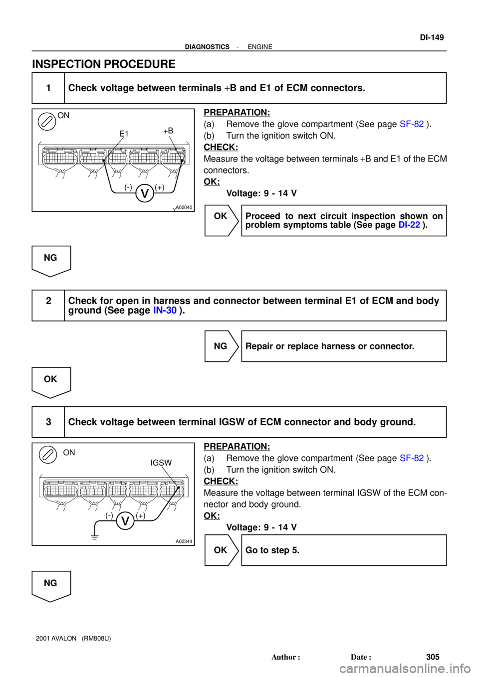
1 Check voltage between terminals +B and E1 of ECM connectors.
PREPARATION:
(a) Remove the glove compartment (See page SF-82).
(b) Turn the ignition switch ON.
CHECK:
Measure the voltage between terminals +B and E1 of the ECM
connectors.
OK:
Voltage: 9 - 14 V
OK Proceed to next circuit inspection shown on
problem symptoms table (See page DI-22).
NG
2 Check for open in harness and connector between terminal E1 of ECM and body
ground (See page IN-30).
NG Repair or replace harness or connector.
OK
3 Check voltage between terminal IGSW of ECM connector and body ground.
PREPARATION:
(a) Remove the glove compartment (See page SF-82).
(b) Turn the ignition switch ON.
CHECK:
Measure the voltage between terminal IGSW of the ECM con-
nector and body ground.
OK:
Voltage: 9 - 14 V
OK Go to step 5.
NG
Page 896 of 1897
A02345
ON
MREL
(-) (+)
DI-150
- DIAGNOSTICSENGINE
306 Author�: Date�:
2001 AVALON (RM808U)
4 Check AM2 fuse (See page DI-1 17, step 10).
NG Check for short in all harness and components
connected to AM2 fuse.
OK
5 Check ignition switch (See page BE-16).
NG Replace ignition switch.
OK
Check and repair harness and connector be-
tween battery and ignition switch, and igni-
tion switch and ECM.
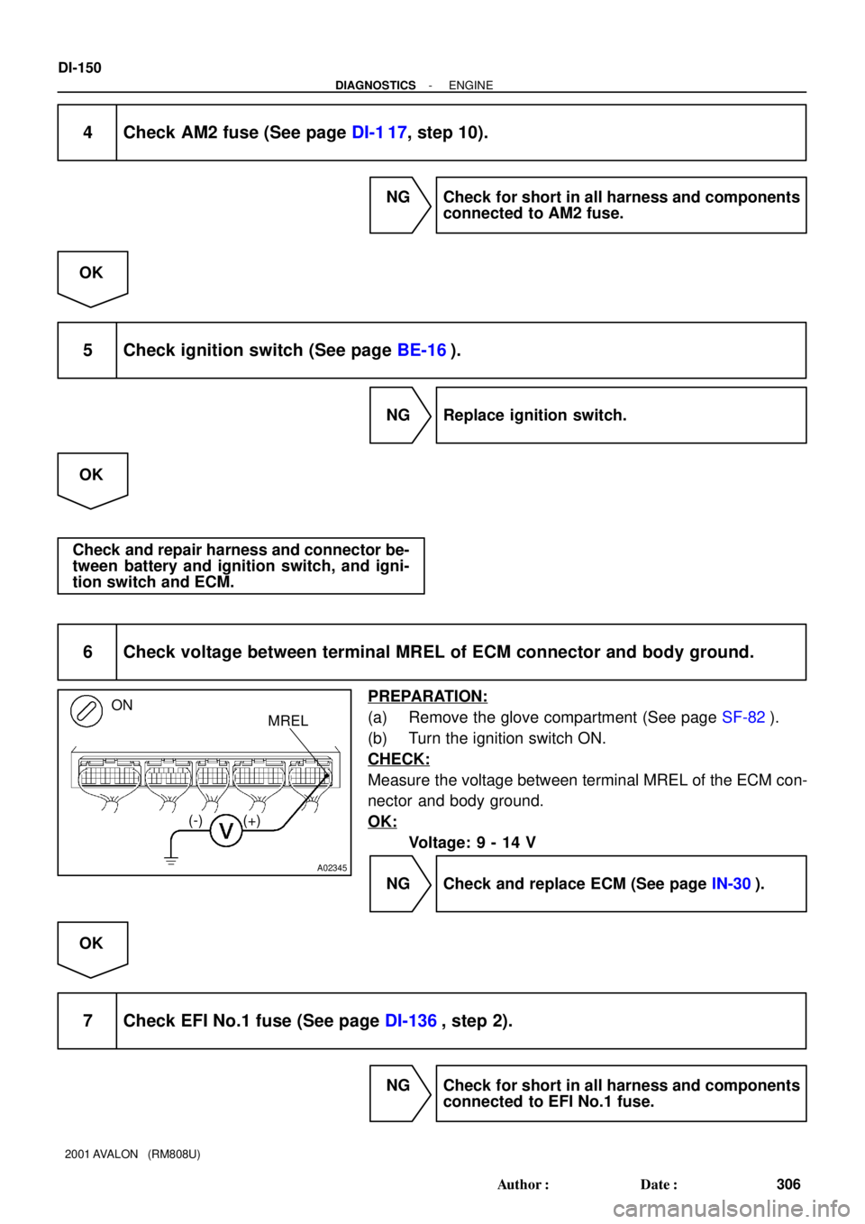
6 Check voltage between terminal MREL of ECM connector and body ground.
PREPARATION:
(a) Remove the glove compartment (See page SF-82).
(b) Turn the ignition switch ON.
CHECK:
Measure the voltage between terminal MREL of the ECM con-
nector and body ground.
OK:
Voltage: 9 - 14 V
NG Check and replace ECM (See page IN-30).
OK
7 Check EFI No.1 fuse (See page DI-136, step 2).
NG Check for short in all harness and components
connected to EFI No.1 fuse.
Page 898 of 1897
A11425
EFI No.1
FL
MainIG Switch
AM2
BatteryEFI Relay
C/OPN Relay
Fuel Pump
ST
RelayStarter Park/ Neutral
Position SwitchECM
FC
Tr
STA
NE (STA Signal)
(NE Signal) MAINMREL
IGSW
ST DI-152
- DIAGNOSTICSENGINE
308 Author�: Date�:
2001 AVALON (RM808U)
Fuel Pump Control Circuit
CIRCUIT DESCRIPTION
In the diagram below, when the engine is cranked, current flows from terminal ST of the ignition switch to
the starter relay (Marking: ST) coil and also current flows to terminal STA of ECM (STA signal).
When the STA signal and NE signal are input to the ECM, Tr is turned ON, current flows to coil of the circuit
opening relay (Marking: C/OPN), the relay switches on, power is supplied to the fuel pump and the fuel pump
operates.
While the NE signal is generated (engine running), the ECM keeps Tr ON (circuit opening relay ON) and the
fuel pump also keeps operating.
DI6TE-01


(NE Signal) MAINMREL
IGSW
ST DI-152
- DIAGNOSTICS")