Page 957 of 1897

(-)
B00802B01504A10956
ON
E2
PTNK
Vacuum Disconnect(-)(+)
Disconnect
Vacuum Type A
Type B
DI-78
- DIAGNOSTICSENGINE
234 Author�: Date�:
2001 AVALON (RM808U)
OK
9 Check voltage be")
A02022
ON
VC E2
(+)
(-)
B00802B01504A10956
ON
E2
PTNK
Vacuum Disconnect(-)(+)
Disconnect
Vacuum Type A
Type B
DI-78
- DIAGNOSTICSENGINE
234 Author�: Date�:
2001 AVALON (RM808U)
OK
9 Check voltage between terminals VC and E2 of ECM connector.
CHECK:
(a) Remove the grove compartment (See page SF-82).
(b) Turn the ignition switch ON.
CHECK:
Measure the voltage between terminals VC and E2 of the ECM
connector.
OK:
Voltage: 4.5 - 5.5 V
NG Check and replace ECM (See page IN-30).
OK
10 Check voltage between terminals PTNK and E2 of ECM connectors.
PREPARATION:
(a) Remove the grove compartment (See page SF-82).
(b) Turn the ignition switch ON.
CHECK:
Measure the voltage between terminals PTNK and E2 of the
ECM connectors.
(1) Disconnect the vacuum hose from the vapor pres-
sure sensor.
(2) Using the MITYVAC (Hand-Held Vacuum Pump),
apply a vacuum of 4.0 kPa (30 mmHg, 1.18 in.Hg)
to the vapor pressure sensor.
NOTICE:
The vacuum applied to the vapor pressure sensor must be
less than 66.7 kPa (500 mmHg, 19.7 in.Hg).
OK:
(1) Voltage: 2.9 - 3.7 V
(2) Voltage: 0.5 V or less
OK Go to step 12.
NG
Page 964 of 1897

(b) Check the vacuum hose for looseness and disconnection.
(c) Check")
A10150A10149BE6653
A10281VSV is ONVSV is OFF ON
Air
FAir
E
F E
- DIAGNOSTICSENGINE
DI-85
241 Author�: Date�:
2001 AVALON (RM808U)
(b) Check the vacuum hose for looseness and disconnection.
(c) Check the vacuum hose for cracks, hole, damage and blockage.
NG Repair or replace.
OK
15 Check operation of VSV for EVAP (See page SF-65).
OK Go to step 16.
NG
Replace VSV and charcoal canister, and then clean vacuum hoses between throttle body and
VSV for EVAP, and VSV for EVAP and charcoal canister.
16 Check for open and short in harness and connector between EFI main relay
(Marking: EFI) and VSV for EVAP, and VSV for EVAP and ECM (See page
IN-30).
NG Repair or replace harness or connector.
OK
Check and replace ECM (See page IN-30).
17 Check VSV for CCV.
PREPARATION:
(a) Connect the TOYOTA hand-held tester to the DLC3.
(b) Disconnect the vacuum hose for the VSV for the CCV
from the charcoal canister.
(c) Turn the ignition switch ON and push the TOYOTA hand-
held tester main switch ON.
(d) Select the ACTIVE TEST mode on the TOYOTA hand-
held tester.
Page 966 of 1897

OK
Check and replace ECM (See page IN-30).
21 Check VSV for pressure")
BE6653A10143A10144A10801VSV is ONVSV is OFF ON
Air
Air
E
FE
F
- DIAGNOSTICSENGINE
DI-87
243 Author�: Date�:
2001 AVALON (RM808U)
OK
Check and replace ECM (See page IN-30).
21 Check VSV for pressure switching valve.
PREPARATION:
(a) Connect the TOYOTA hand-held tester to the DLC3.
(b) Turn the ignition switch ON and push the TOYOTA hand-
held tester main switch ON.
(c) Select the ACTIVE TEST mode on the TOYOTA hand-
held tester.
CHECK:
Check the VSV operation when it is operated by the TOYOTA
hand-held tester.
OK:
VSV is ON:
Air from port E flows out through port F.
VSV is OFF:
Air does not flow from port E to port F.
OK Go to step 24.
NG
22 Check operation of VSV for pressure switching valve (See page SF-72).
OK Go to step 23.
NG
Replace VSV and charcoal canister, and then clean vacuum hoses between charcoal canister
and VSV for pressure switching valve, and VSV for pressure switching valve and fuel tank.
23 Check for open and short in harness and connector between EFI main relay
(Marking: EFI) and VSV for pressure switching valve, and VSV for pressure
switching valve and ECM (See page IN-30).
Page 972 of 1897

13 Check VSV for EVAP.
PREPARATION:
(a) Remove the glove compartment (See")
A02028
ON
EVP1
Air
Air
F
F E
E ONOFF
VSV is ON
VSV is OFF
- DIAGNOSTICSENGINE
DI-93
249 Author�: Date�:
2001 AVALON (RM808U)
13 Check VSV for EVAP.
PREPARATION:
(a) Remove the glove compartment (See page SF-82).
(b) Turn the ignition switch ON.
CHECK:
Check the VSV function.
(1) Connect between terminal EVP1 of the ECM con-
nector and body ground (ON).
(2) Disconnect between terminal EVP1 of the ECM
connector and body ground (OFF).
OK:
(1) VSV is ON:
Air from port E flows out through port F.
(2) VSV is OFF:
Air does not flow from port E to port F.
OK Go to step 16.
NG
14 Check operation of VSV for EVAP (See page SF-65).
OK Go to step 15.
NG
Replace VSV and clean vacuum hoses between throttle body and VSV for EVAP, and VSV for
EVAP and charcoal canister, and then check charcoal canister.
15 Check for open and short in harness and connector between EFI main relay
(Marking: EFI) and VSV for EVAP, and VSV for EVAP and ECM (See page
IN-30).
NG Repair or replace harness or connector.
Page 973 of 1897
BE6653
A10281A10310
A10951
VSV is ON
VSV is OFF ON
CCV
OFF ON
Air
E Air
E
FF
DI-94
- DIAGNOSTICSENGINE
250 Author�: Date�:
2001 AVALON (RM808U)
OK
Check and replace ECM (See page IN-30).
16 Check VSV for CCV.
PREPARATION:
(a) Remove the grove compartment (See page SF-82).
(b) Turn the ignition switch ON.
CHECK:
Check the VSV function.
(1) Connect between terminal CCV of the ECM con-
nector and body ground (ON).
(2) Disconnect between terminal CCV of the ECM con-
nector and body ground (OFF).
OK:
VSV is ON:
Air does not flow from port E to port F.
VSV is OFF:
Air from port E flows out through port F.
OK Go to step 19.
NG
17 Check operation of VSV for CCV (See page SF-70).
OK Go to step 18.
NG
Replace VSV and charcoal canister, and then
clean vacuum hose between charcoal canis-
ter and VSV for CCV.
Page 974 of 1897
BE6653
A10278A10604A10952
VSV is ONVSV is OFF ON
TBP
OFFON
Air
E Air
E
FF
- DIAGNOSTICSENGINE
DI-95
251 Author�: Date�:
2001 AVALON (RM808U)
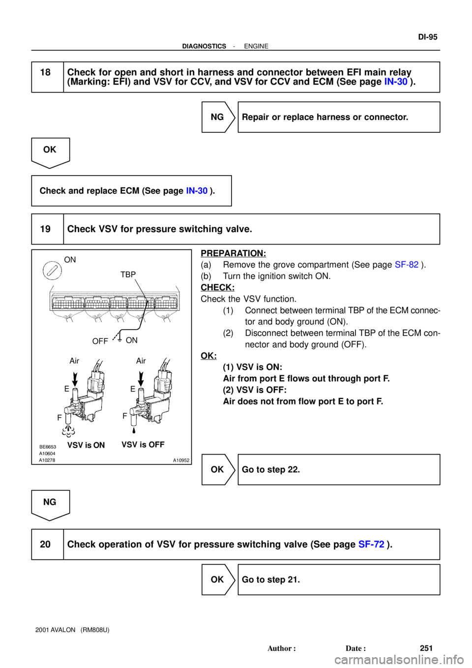
18 Check for open and short in harness and connector between EFI main relay
(Marking: EFI) and VSV for CCV, and VSV for CCV and ECM (See page IN-30).
NG Repair or replace harness or connector.
OK
Check and replace ECM (See page IN-30).
19 Check VSV for pressure switching valve.
PREPARATION:
(a) Remove the grove compartment (See page SF-82).
(b) Turn the ignition switch ON.
CHECK:
Check the VSV function.
(1) Connect between terminal TBP of the ECM connec-
tor and body ground (ON).
(2) Disconnect between terminal TBP of the ECM con-
nector and body ground (OFF).
OK:
(1) VSV is ON:
Air from port E flows out through port F.
(2) VSV is OFF:
Air does not from flow port E to port F.
OK Go to step 22.
NG
20 Check operation of VSV for pressure switching valve (See page SF-72).
OK Go to step 21.
Page 979 of 1897
 (+)
DI-100
- DIAGNOSTICSENGINE
256 Author�: Date�:
2001 AVALON (RM808U)
1 Check operation of speedometer.
CHECK:
Drive the vehicle and check if t")
A02030
E7 Connector
SPD
A02029
E7 ConnectorON
SPD(-) (+)
DI-100
- DIAGNOSTICSENGINE
256 Author�: Date�:
2001 AVALON (RM808U)
1 Check operation of speedometer.
CHECK:
Drive the vehicle and check if the operation of the speedometer in the combination meter is normal.
HINT:
The vehicle speed sensor is operating normally if the speedometer display is normal.
NG Check speedometer circuit (See page BE-43).
OK
2 Check for short in harness and connector between terminal SPD of ECM and
body ground.
PREPARATION:
(a) Remove the glove compartment (See page SF-83).
(b) Disconnect the E7 connector from the ECM.
CHECK:
Check the continuity between terminal SPD of the ECM con-
nector and body ground.
OK:
No continuity (1 MW or higher)
NG Repair or replace harness or connector.
OK
3 Check voltage between terminal SPD of ECM connector and body ground.
PREPARATION:
(a) Remove the glove compartment (See page SF-83).
(b) Disconnect the E7 connector from the ECM.
(c) Turn the ignition switch ON.
CHECK:
Measure the voltage between terminal SPD of the ECM con-
nector and body ground.
OK:
Voltage: 9 - 14 V
NG Check for open in harness and connector be-
tween J/B No.3 and ECM (See page IN-30).
Page 982 of 1897
 (-)
- DIAGNOSTICSENGINE
DI-103
259 Author�: Date�:
2001 AVALON (RM808U)
1 Check idle speed.
When using TOYOTA hand-held tester:
PREPARATION:
(a) Warm up the engine to")
A07628
ON
RSOE4 Connector
(+) (-)
- DIAGNOSTICSENGINE
DI-103
259 Author�: Date�:
2001 AVALON (RM808U)
1 Check idle speed.
When using TOYOTA hand-held tester:
PREPARATION:
(a) Warm up the engine to normal operating temperature.
(b) Switch off all the accessories.
(c) Switch off the A/C.
(d) Shift transmission into the N range or neutral position.
(e) Connect the TOYOTA hand-held tester to the DLC3 on the vehicle and select the ACTIVE TEST
mode.
CHECK:
Check the difference of the engine speed between the ones, less than 5 sec. and more than 5 sec. after
switching the TE1 from OFF to ON by the TOYOTA hand-held tester.
OK:
Difference of engine speed: More than 100 rpm
When not using TOYOTA hand-held tester:
PREPARATION:
(a) Warm up the engine to normal operating temperature.
(b) Switch off all the accessories.
(c) Switch off the A/C.
(d) Shift transmission into the N range or neutral position.
(e) Connect the OBDII scan tool to DLC3 on the vehicle.
(f) Using SST, connect terminals TE1 and E1 of the DLC1.
SST 09843-18020
CHECK:
Check the difference of engine speed between the ones, less than 5 sec. and more than 5 sec. after connect-
ing terminals TE1 and E1 of the DLC1.
OK:
Difference of engine speed: More than 100 rpm
OK Go to step 6.
NG
2 Check voltage between terminal RSO of ECM connector and body ground.
PREPARATION:
(a) Remove the glove compartment (See page SF-83).
(b) Disconnect the E4 connector from the ECM.
(c) Turn the ignition switch ON.
CHECK:
Measure the voltage between terminal RSO of the ECM con-
nector and body ground.
OK:
Voltage: 9 - 14 V