Page 899 of 1897
A11672
From
Terminal
MREL of
ECM From
Battery1 5
2 B-R3
C/OPN Relay Driver Side R/B No.6
6
66 6 B-R 1
IF1 W-R
W-B
2C
2F13
EFI
No.1 AM2
EFI Relay 5
1B
EDEngine Room J/B
43
22B
1 2G
46 7
2C 2
BK 7 4
IF1ECM
E01
ID2E8
Fuel
Pump
AL-B
W-BJ11
J/CFC
G-B3
5 41
L-B B-O IG SwitchW-B
W-R
L-O
BE6653A02330
A02405
ON
- DIAGNOSTICSENGINE
DI-153
309 Author�: Date�:
2001 AVALON (RM808U)
WIRING DIAGRAM
INSPECTION PROCEDURE
TOYOTA hand-held tester:
1 Connect TOYOTA hand-held tester, and check operation of fuel pump.
PREPARATION:1
(a) Connect the TOYOTA hand-held tester to the DLC3.
(b) Turn the ignition switch ON and push the TOYOTA hand-
held tester main switch ON.
(c) Use the ACTIVE TEST mode to operate the fuel pump.
CHECK:
Check that the pulsation damper screw rises up when the fuel
pump is operated by the TOYOTA hand-held tester.
OK:
The pulsation damper screw rises up.
OK Check for starter signal circuit
(See page DI-142).
NG
Page 900 of 1897
A02064
ON
FC
(+) (-)
DI-154
- DIAGNOSTICSENGINE
310 Author�: Date�:
2001 AVALON (RM808U)
2 Check for ECM power source circuit (See page DI-148).
NG Repair or replace.
OK
3 Check circuit opening relay (Marking: C/OPN) (See page SF-63).
NG Replace circuit opening relay.
OK
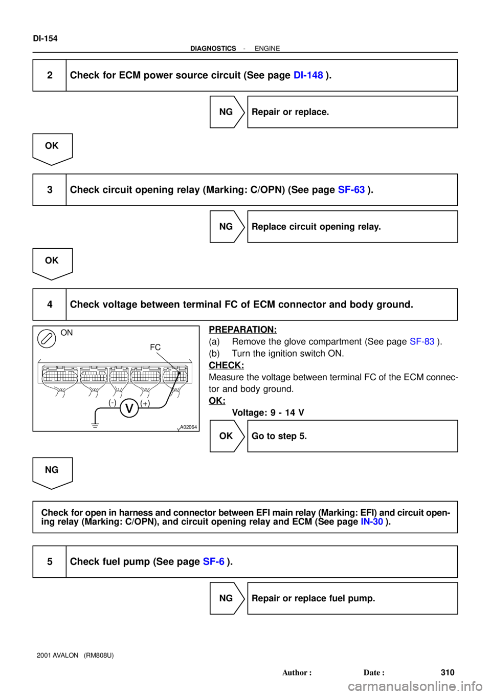
4 Check voltage between terminal FC of ECM connector and body ground.
PREPARATION:
(a) Remove the glove compartment (See page SF-83).
(b) Turn the ignition switch ON.
CHECK:
Measure the voltage between terminal FC of the ECM connec-
tor and body ground.
OK:
Voltage: 9 - 14 V
OK Go to step 5.
NG
Check for open in harness and connector between EFI main relay (Marking: EFI) and circuit open-
ing relay (Marking: C/OPN), and circuit opening relay and ECM (See page IN-30).
5 Check fuel pump (See page SF-6).
NG Repair or replace fuel pump.
Page 901 of 1897
A02042
ON
FC
- DIAGNOSTICSENGINE
DI-155
311 Author�: Date�:
2001 AVALON (RM808U)
OK
6 Check for open in harness and connector between circuit opening relay (Mark-
ing: C/OPN) and fuel pump, and fuel pump and body ground
(See page IN-30).
NG Repair or replace harness or connector.
OK
Check and replace ECM (See page IN-30).
OBD II scan tool (excluding TOYOTA hand-held tester):
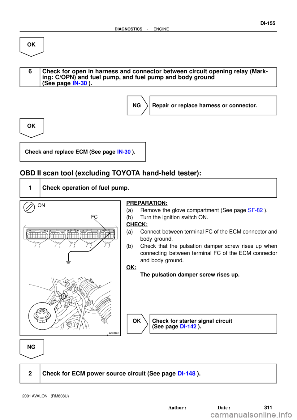
1 Check operation of fuel pump.
PREPARATION:
(a) Remove the glove compartment (See page SF-82).
(b) Turn the ignition switch ON.
CHECK:
(a) Connect between terminal FC of the ECM connector and
body ground.
(b) Check that the pulsation damper screw rises up when
connecting between terminal FC of the ECM connector
and body ground.
OK:
The pulsation damper screw rises up.
OK Check for starter signal circuit
(See page DI-142).
NG
2 Check for ECM power source circuit (See page DI-148).
Page 902 of 1897
A02064
ON
FC
(+) (-)
DI-156
- DIAGNOSTICSENGINE
312 Author�: Date�:
2001 AVALON (RM808U)
NG Repair or replace.
OK
3 Check circuit opening relay (Marking: C/OPN) (See page SF-63).
NG Replace circuit opening relay.
OK
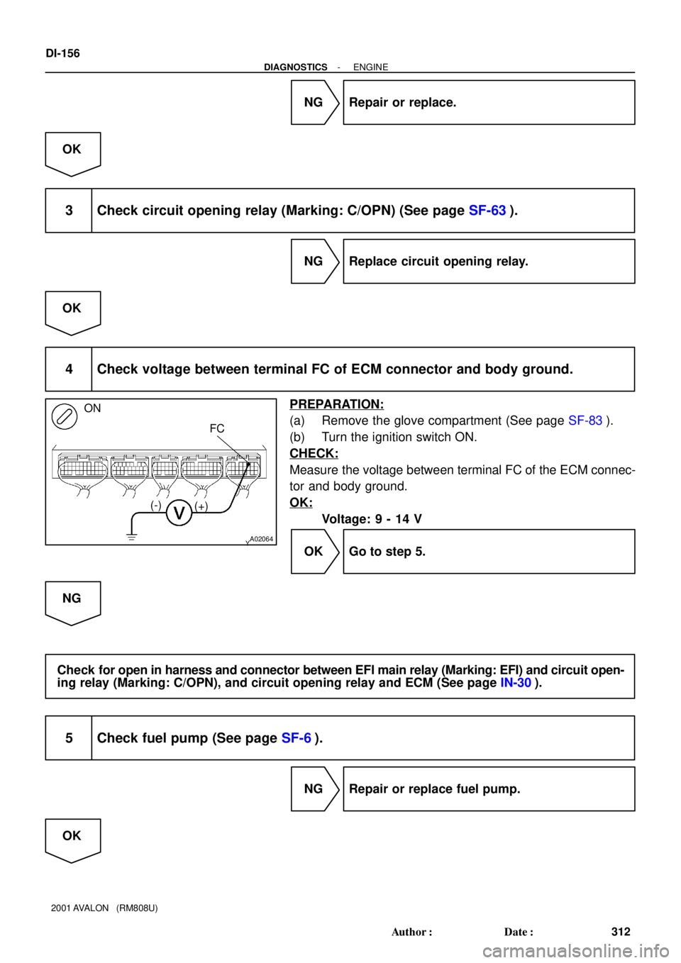
4 Check voltage between terminal FC of ECM connector and body ground.
PREPARATION:
(a) Remove the glove compartment (See page SF-83).
(b) Turn the ignition switch ON.
CHECK:
Measure the voltage between terminal FC of the ECM connec-
tor and body ground.
OK:
Voltage: 9 - 14 V
OK Go to step 5.
NG
Check for open in harness and connector between EFI main relay (Marking: EFI) and circuit open-
ing relay (Marking: C/OPN), and circuit opening relay and ECM (See page IN-30).
5 Check fuel pump (See page SF-6).
NG Repair or replace fuel pump.
OK
Page 905 of 1897

INSPECTION PROCEDURE
TOYOTA hand-held tester:
1 Conn")
A00307
ON
VSV is ON VSV is OFF
Air Filter Air
Air
E
FE
F
BE6653
FI7073 FI7074
DI-146
- DIAGNOSTICSENGINE
302 Author�: Date�:
2001 AVALON (RM808U)
INSPECTION PROCEDURE
TOYOTA hand-held tester:
1 Connect TOYOTA hand-held tester, and check operation of VSV for ACIS.
PREPARATION:
(a) Remove the fuse cover on the instrument panel.
(b) Connect the TOYOTA hand-held tester to the DLC3.
(c) Turn the ignition switch ON and TOYOTA hand-held tes-
ter main switch ON.
(d) Select the INTAKE CTRL VSV from the ACTIVE TEST
menu on the TOYOTA hand-held tester.
CHECK:
Check the operation of the VSV when the VSV is operated by
the TOYOTA hand-held tester.
OK:
VSV is ON:
Air from port E flows out through port F.
VSV is OFF:
Air from port E flows out through the air filter.
OK Check vacuum tank (See page SF-46).
NG
2 Check VSV for ACIS (See page SF-68).
NG Replace VSV for ACIS.
OK
3 Check for open and short in harness and connector between EFI main relay
(Marking: EFI) and ECM (See page IN-30).
NG Repair or replace harness or connector.
OK
Page 906 of 1897
A11824
ON
ACIS
(+)
(-)ACI1
- DIAGNOSTICSENGINE
DI-147
303 Author�: Date�:
2001 AVALON (RM808U)
Check and replace ECM (See page IN-30).
OBD II scan tool (excluding TOYOTA hand-held tester):
1 Check VSV for ACIS (See page SF-68).
NG Replace VSV for ACIS.
OK
2 Check voltage between terminals ACIS, ACI1 of ECM connector and body
ground.
PREPARATION:
(a) Remove the glove compartment (See page SF-82).
(b) Turn the ignition switch ON.
CHECK:
Measure the voltage between terminals ACIS, ACI1 of the ECM
connector and body ground.
OK:
Voltage: 9 - 14 V
NG Check for open and short in harness and con-
nector between EFI main relay (Marking: EFI)
and ECM (See page IN-30).
OK
3 Check vacuum tank (See page SF-58).
NG Repair or replace.
OK
Check and replace ECM (See page IN-30).
Page 907 of 1897

CIRCUIT INSPECTION
DTC P0100 Mass")
DI07F-09
A06106
B+
Thermister
Power Transister
Platinum Hot Wire
B
Output
Voltage A
FI6929
S05741
- DIAGNOSTICSENGINE
DI-23
179 Author�: Date�:
2001 AVALON (RM808U)
CIRCUIT INSPECTION
DTC P0100 Mass Air Flow Circuit Malfunction
CIRCUIT DESCRIPTION
The mass air flow meter uses a platinum hot wire. The hot wire air flow meter consists of a platinum hot wire,
thermistor and a control circuit installed in a plastic housing. The hot wire air flow meter works on the principle
that the hot wire and thermistor located in the intake air bypass of the housing detect any changes in the
intake air temperature.
The hot wire is maintained at the set temperature by controlling the current flow through the hot wire. This
current flow is then measured as the output voltage of the air flow meter.
The circuit is constructed so that the platinum hot wire and thermistor provide a bridge circuit with the power
transistor controlled so that the potential of A and B remains equal to maintain the set temperature.
DTC No.DTC Detecting ConditionTrouble Area
P0100Open or short in mass air flow meter circuit with more than 3
sec. engine speed 4,000 rpm or less�Open or short in mass air flow meter circuit
�Mass air flow meter
�ECM
If the ECM detects DTC P0100 it operates the fail-safe function, keeping the ignition timing and injection
volume constantly and making it possible to drive the vehicle.
HINT:
After confirming DTC P0100, use the OBD II scan tool or TOYOTA hand-held tester to confirm the mass
air flow ratio from the CURRENT DATA.
Mass Air Flow Value (gm/sec.)Malfunction
0.0�Mass air flow meter power source circuit open
�VG circuit open or short
271.0 or more�E2G circuit open
Page 908 of 1897

A11668
Engine Room J/B
EFI No.1
2G
2B 2A
2F2
5
1 3
2B-W
4L-O
4 2
EFI No.2 EFI Relay
From BatteryB
Mass Air
Flow Meter3
2 1
EDW-B
R-BECM
E2GVG
E2 R10
19
E5E5
From
Terminal
MREL of
ECM
DI-24
- DIAGNOSTICSENGINE
180 Author�: Date�:
2001 AVALON (RM808U)
WIRING DIAGRAM
INSPECTION PROCEDURE
HINT:
Read freeze frame data using TOYOTA hand-held tester or OBD II scan tool. Because freeze frame records
the engine conditions when the malfunction is detected. When troubleshooting, it is useful for determining
whether the vehicle was running or stopped, the engine was warmed up or not, the air-fuel ratio was lean
or rich, etc. at the time of the malfunction.
1 Connect OBD II scan tool or TOYOTA hand-held tester, and read value of mass
air flow rate.
PREPARATION:
(a) Connect the OBD II scan tool or TOYOTA hand-held tester to the DLC3.
(b) Turn the ignition switch ON and push the OBD II scan tool or TOYOTA hand-held tester main switch
ON.
(c) Start the engine.
CHECK:
Read the mass air flow rate on the OBD II scan tool or TOYOTA hand-held tester.
RESULT:
Type IType II
Mass Air Flow Rate (gm/sec.)0.0271.0 or more
Type I Go to step 2.
Type II Go to step 5.