Page 850 of 1897
I00311
4
3
- DIAGNOSTICSCRUISE CONTROL SYSTEM
DI-565
721 Author�: Date�:
2001 AVALON (RM808U)
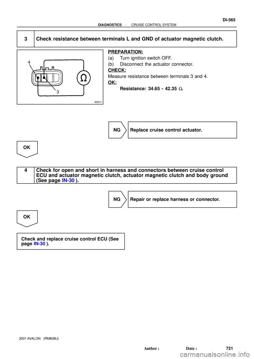
3 Check resistance between terminals L and GND of actuator magnetic clutch.
PREPARATION:
(a) Turn ignition switch OFF.
(b) Disconnect the actuator connector.
CHECK:
Measure resistance between terminals 3 and 4.
OK:
Resistance: 34.65 - 42.35 W.
NG Replace cruise control actuator.
OK
4 Check for open and short in harness and connectors between cruise control
ECU and actuator magnetic clutch, actuator magnetic clutch and body ground
(See page IN-30).
NG Repair or replace harness or connector.
OK
Check and replace cruise control ECU (See
page IN-30).
Page 851 of 1897
I00055
4
3(+)
(-)
DI-566
- DIAGNOSTICSCRUISE CONTROL SYSTEM
722 Author�: Date�:
2001 AVALON (RM808U)
DTC 14 Actuator Mechanical Malfunction
CIRCUIT DESCRIPTION
The circuit detects the rotation position of the actuator control plate and sends a signal to the ECU.
DTC No.Detection ItemTrouble Area
14Cruise control actuator mechanical malfunction.
�Actuator lock: (motor, arm)
�Actuator motor
�Cruise control ECU
WIRING DIAGRAM
See page DI-563.
INSPECTION PROCEDURE
1 Check cruise control actuator arm locking operation
PREPARATION:
(a) Turn ignition switch OFF.
(b) Disconnect the actuator connector.
CHECK:
(a) Connect the positive (+) lead from the battery to the termi-
nal 3 of actuator and the negative (-) lead to terminal 4.
NOTICE:
Do not connect the high tension cables to the wrong bat-
tery terminal. The cruise control actuator will be damaged.
(b) Move the control plate by hand.
OK:
Control plate doesn't move.
NG Replace cruise control actuator.
OK
DI08O-14
Page 852 of 1897
I03209
Fully open side
Fully Closed sideControl plate
Control plate(+)
(-) (+)
(-) 4
321
4
3
21
- DIAGNOSTICSCRUISE CONTROL SYSTEM
DI-567
723 Author�: Date�:
2001 AVALON (RM808U)
2 Check cruise control actuator operation.
PREPARATION:
(a) Turn ignition switch OFF.
(b) Disconnect the actuator connector.
CHECK:
Connect the positive (+) lead from the battery to terminals 1 and
3 of actuator, connect the negative (-) lead to terminals 2 and
4 of actuator.
OK:
Control arm moves to fully open side
CHECK:
Connect the positive (+) lead from the battery to terminals 2 and
3 of actuator, connect the negative (-) lead to terminals 1 and
4 of actuator.
OK:
Control arm moves to fully colsed side
NG Replace cruise control actuator.
OK
3 Check harness and connector between cruise control ECU and cruise control ac-
tuator (See page IN-30).
NG Repair or replace harness or connector.
OK
Check and replace cruise control ECU (See
page IN-30).
Page 858 of 1897
 (+)
- DIAGNOSTICSCRUIS")
Input SignalIndicator Light
Blinking Pattern
SET/COAST
switch
RESUME/ACCEL
switch
CANCEL switch2 Pulses
ON
OFF
ON
OFF3 Pulses
ON
OFFSW OFF
SW ON
AB0119
I00168
I00171
ON
CCS
(-) (+)
- DIAGNOSTICSCRUISE CONTROL SYSTEM
DI-573
729 Author�: Date�:
2001 AVALON (RM808U)
INSPECTION PROCEDURE
1 Input signal check.
PREPARATION:
See input signal check on page DI-551.
CHECK:
Check the indicator light operation when each of the SET/
COAST, RESUME/ACCEL and CANCEL is turned on.
OK:
SET/COAST, RESUME/ACCEL switch
The signals shown in the table on the left should be
output when each switch is ON. The signal should
disappear when the switch is turned OFF.
CANCEL switch
The indicator light goes off when the cancel switch is
turned ON.
OK Wait and see.
NG
2 Check voltage between terminals CCS of cruise control ECU connector and body
ground.
PREPARATION:
(a) Remove the ECU with connector still connected.
(b) Turn ignition switch ON.
CHECK:
Measure voltage between terminals 18 of ECU connector and
body ground, when each of the SET/COAST, RESUME/AC-
CEL and CANCEL is turned ON.
Switch positionResistance (V)
Neutral10 - 16 V
MAINBelow 1V
REST/ACC4.7 - 7.7 V
SET/COAST2.6 - 4.2 V
NG Proceed to next circuit inspection shown in
problem symptom table (See page DI-560)
OK
Page 861 of 1897
AB0119
I00167
I00172
ON
IDL
(-) (+)
DI-576
- DIAGNOSTICSCRUISE CONTROL SYSTEM
732 Author�: Date�:
2001 AVALON (RM808U)
INSPECTION PROCEDURE
1 Check voltage between terminal IDL of cruise control ECU connector and body
ground.
PREPARATION:
(a) Remove the ECU with connector still connected.
(b) Disconnect the ECM connector.
(c) Turn ignition switch ON.
CHECK:
Measure voltage between terminal IDL of ECU connector and
body ground when the throttle valve is fully closed and fully
opened.
OK:
Throttle valve positionVoltage
Fully opened10 - 14 V
Fully closedBelow 2 V
OK Proceed to next circuit inspection shown in
problem symptom table (See page DI-560).
NG
2 Check harness and connector between ECM and throttle position sensor (See
page IN-30).
NG Repair or replace harness or connector.
OK
3 Check throttle position sensor circuit (See page DI-38).
NG Replace throttle position sensor.
OK
Page 864 of 1897
AB0119
I00145
I00177
ON
CAN
(-) (+)
DI-590
- DIAGNOSTICSCRUISE CONTROL SYSTEM
746 Author�: Date�:
2001 AVALON (RM808U)
Cancel Switch Circuit (Cruise Control Switch)
CIRCUIT DESCRIPTION
When the cruise control cancel switch is turned ON, the cruise control does not operate.
WIRING DIAGRAM
See page DI-572.
INSPECTION PROCEDURE
1 Check voltage between terminal CAN of cruise control ECU connector and body
ground.
PREPARATION:
(a) Remove the ECU with connector still connected.
(b) Turn ignition switch ON.
CHECK:
Measure voltage between terminal CAN of cruise control ECU
connector when main switch is held ON and OFF.
OK:
Main switchVoltage
OFF10 - 14 V
ONBelow 0.5 V
OK Proceed to next circuit inspection shown on
problem symptom table (See page DI-560).
NG
DI6L8-01
Page 866 of 1897
I13610
Cruise Control ECU
4
PI
R-B
W-B10
1D
IF17W-R
4 IG1 AM1Ignition Switch 2
W
AM1 GAUGE NO. 1
2 1
5
B-L1
ALTFL Block
1 B
FL MAIN
BatteryF8 2G1
F6 F10
1
1
2H
B 5
W-LW-L 1
43 3
1B1
1G
4
1C IG1 RERAY 4
4D13
4F4
M7 M64
4H17
4A17
GR-R
R-BGR-R Cruise Control
Indicator Light
(in Multi Display)
IG
C15
I15
2J/B No. 4 J/B No. 4
Driver Side J/B
Engine Room R/B No. 5
Engine Room J/B DI-592
- DIAGNOSTICSCRUISE CONTROL SYSTEM
748 Author�: Date�:
2001 AVALON (RM808U)
CRUISE MAIN Indicator Light Circuit
CIRCUIT DESCRIPTION
When the cruise control main switch is turned ON, CRUISE MAIN indicator light lights up.
WIRING DIAGRAM
DI090-28
Page 867 of 1897
AB0119
I00144
I00178
ON
PI
(-) (+)
- DIAGNOSTICSCRUISE CONTROL SYSTEM
DI-593
749 Author�: Date�:
2001 AVALON (RM808U)
INSPECTION PROCEDURE
1 Check voltage between terminals PI and GND of cruise control ECU connector.
PREPARATION:
Tun ignition switch ON.
CHECK:
Measure voltage between terminals PI and GND of cruise con-
trol ECU connector when main switch is ON and OFF.
OK:
Switch positionVoltage
OFF10 - 16 V
ONBelow 1.2 V
OK Proceed to next circuit inspection shown in
problem symptom table (See page DI-560).
NG
2 Check combination meter (See page BE-2).
NG Replace combination meter.
OK
Check and replace cruise control ECU (See
page IN-30).