2001 NISSAN X-TRAIL turn signal
[x] Cancel search: turn signalPage 3333 of 3833
TROUBLE DIAGNOSIS
ATC-57
C
D
E
F
G
H
I
K
L
MA
B
AT C
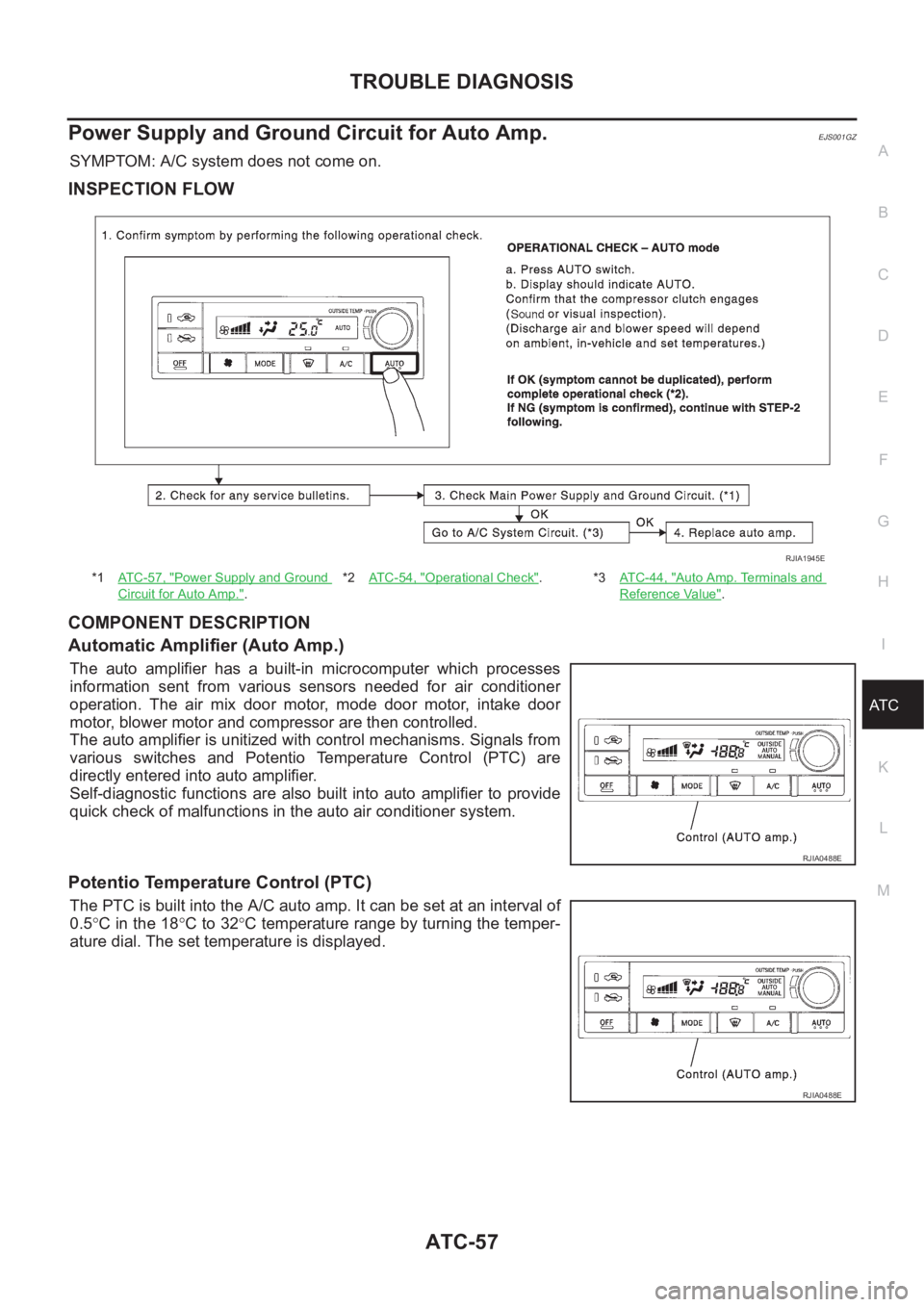
Power Supply and Ground Circuit for Auto Amp.EJS001GZ
SYMPTOM: A/C system does not come on.
INSPECTION FLOW
COMPONENT DESCRIPTION
Automatic Amplifier (Auto Amp.)
The auto amplifier has a built-in microcomputer which processes
information sent from various sensors needed for air conditioner
operation. The air mix door motor, mode door motor, intake door
motor, blower motor and compressor are then controlled.
The auto amplifier is unitized with control mechanisms. Signals from
various switches and Potentio Temperature Control (PTC) are
directly entered into auto amplifier.
Self-diagnostic functions are also built into auto amplifier to provide
quick check of malfunctions in the auto air conditioner system.
Potentio Temperature Control (PTC)
The PTC is built into the A/C auto amp. It can be set at an interval of
0.5°C in the 18°C to 32°C temperature range by turning the temper-
ature dial. The set temperature is displayed.
*1AT C - 5 7 , "Power Supply and Ground
Circuit for Auto Amp.".*2AT C - 5 4 , "
Operational Check".*3AT C - 4 4 , "Auto Amp. Terminals and
Reference Value".
RJIA1945E
RJIA0488E
RJIA0488E
Page 3336 of 3833
ATC-60
TROUBLE DIAGNOSIS
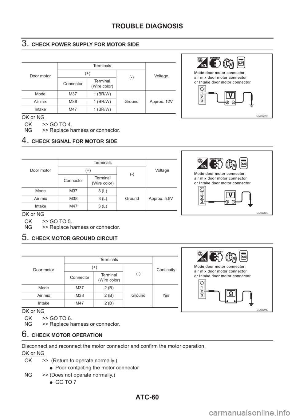
3. CHECK POWER SUPPLY FOR MOTOR SIDE
OK or NG
OK >> GO TO 4.
NG >> Replace harness or connector.
4. CHECK SIGNAL FOR MOTOR SIDE
OK or NG
OK >> GO TO 5.
NG >> Replace harness or connector.
5. CHECK MOTOR GROUND CIRCUIT
OK or NG
OK >> GO TO 6.
NG >> Replace harness or connector.
6. CHECK MOTOR OPERATION
Disconnect and reconnect the motor connector and confirm the motor operation.
OK or NG
OK >> (Return to operate normally.)
●Poor contacting the motor connector
NG >> (Does not operate normally.)
●GO TO 7
Door motorTerminals
Vo l ta g e (+)
(-)
ConnectorTerminal
(Wire color)
Mode M37 1 (BR/W)
Ground Approx. 12V Air mix M38 1 (BR/W)
Intake M47 1 (BR/W)
RJIA0509E
Door motorTerminals
Vo l ta g e (+)
(-)
ConnectorTerminal
(Wire color)
Mode M37 3 (L)
Ground Approx. 5.5V Air mix M38 3 (L)
Intake M47 3 (L)
RJIA0510E
Door motorTerminals
Continuity (+)
(-)
ConnectorTerminal
(Wire color)
Mode M37 2 (B)
Ground Yes Air mix M38 2 (B)
Intake M47 2 (B)
RJIA0511E
Page 3339 of 3833
TROUBLE DIAGNOSIS
ATC-63
C
D
E
F
G
H
I
K
L
MA
B
AT C
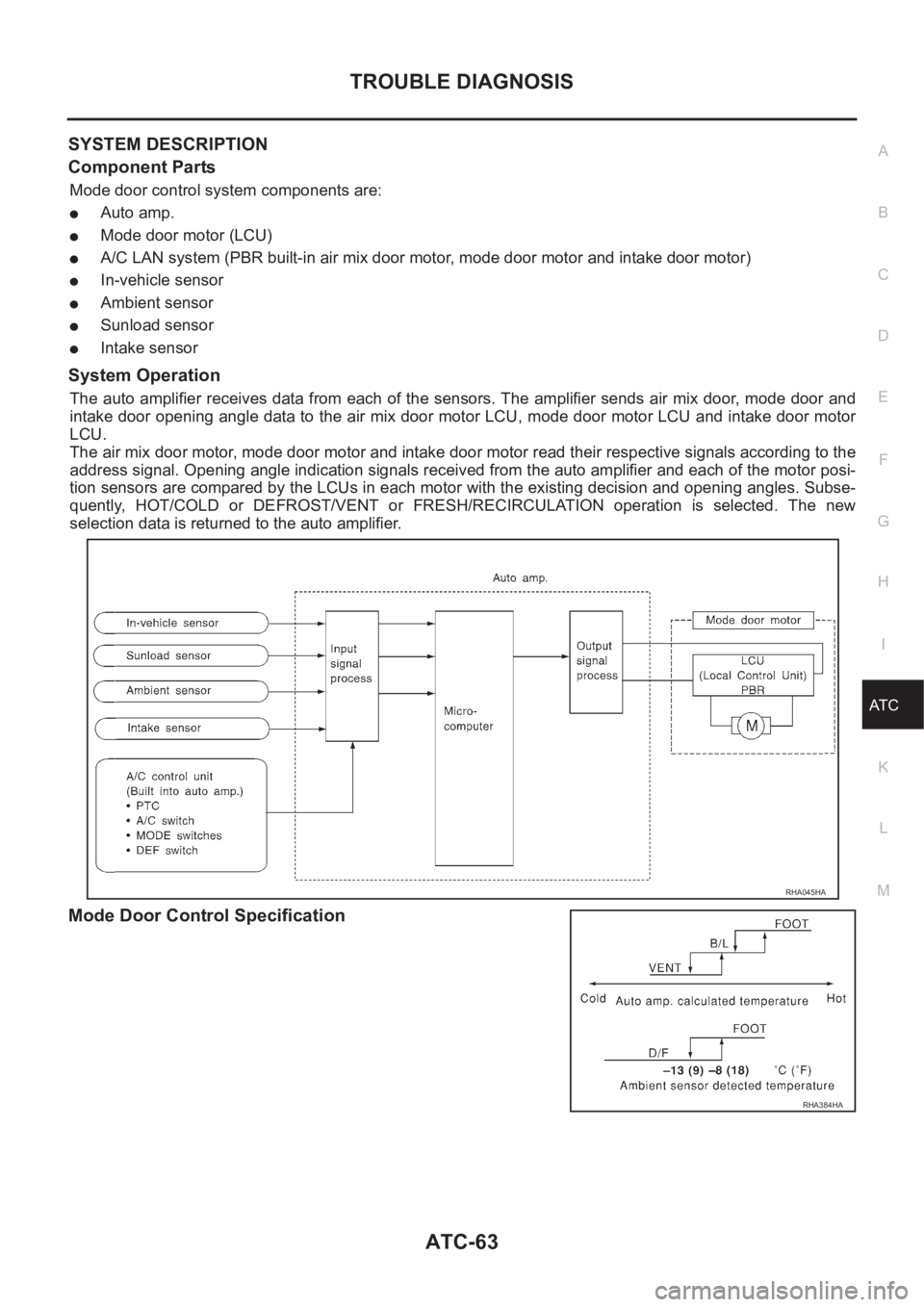
SYSTEM DESCRIPTION
Component Parts
Mode door control system components are:
●Auto amp.
●Mode door motor (LCU)
●A/C LAN system (PBR built-in air mix door motor, mode door motor and intake door motor)
●In-vehicle sensor
●Ambient sensor
●Sunload sensor
●Intake sensor
System Operation
The auto amplifier receives data from each of the sensors. The amplifier sends air mix door, mode door and
intake door opening angle data to the air mix door motor LCU, mode door motor LCU and intake door motor
LCU.
The air mix door motor, mode door motor and intake door motor read their respective signals according to the
address signal. Opening angle indication signals received from the auto amplifier and each of the motor posi-
tion sensors are compared by the LCUs in each motor with the existing decision and opening angles. Subse-
quently, HOT/COLD or DEFROST/VENT or FRESH/RECIRCULATION operation is selected. The new
selection data is returned to the auto amplifier.
Mode Door Control Specification
RHA045HA
RHA384HA
Page 3342 of 3833
ATC-66
TROUBLE DIAGNOSIS
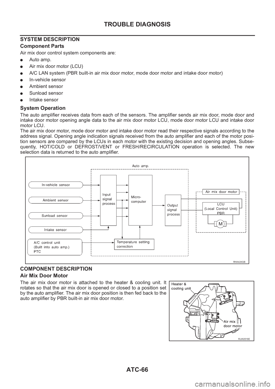
SYSTEM DESCRIPTION
Component Parts
Air mix door control system components are:
●Auto amp.
●Air mix door motor (LCU)
●A/C LAN system (PBR built-in air mix door motor, mode door motor and intake door motor)
●In-vehicle sensor
●Ambient sensor
●Sunload sensor
●Intake sensor
System Operation
The auto amplifier receives data from each of the sensors. The amplifier sends air mix door, mode door and
intake door motor opening angle data to the air mix door motor LCU, mode door motor LCU and intake door
motor LCU.
The air mix door motor, mode door motor and intake door motor read their respective signals according to the
address signal. Opening angle indication signals received from the auto amplifier and each of the motor posi-
tion sensors are compared by the LCUs in each motor with the existing decision and opening angles. Subse-
quently, HOT/COLD or DEFROST/VENT or FRESH/RECIRCULATION operation is selected. The new
selection data is returned to the auto amplifier.
COMPONENT DESCRIPTION
Air Mix Door Motor
The air mix door motor is attached to the heater & cooling unit. It
rotates so that the air mix door is opened or closed to a position set
by the auto amplifier. The air mix door position is then fed back to the
auto amplifier by PBR built-in air mix door motor.
RHA424GB
RJIA0516E
Page 3345 of 3833
TROUBLE DIAGNOSIS
ATC-69
C
D
E
F
G
H
I
K
L
MA
B
AT C
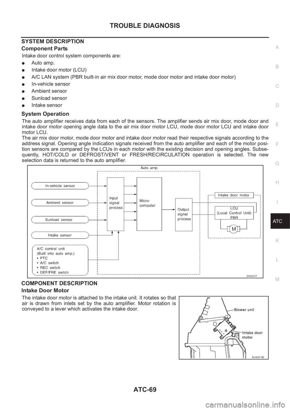
SYSTEM DESCRIPTION
Component Parts
Intake door control system components are:
●Auto amp.
●Intake door motor (LCU)
●A/C LAN system (PBR built-in air mix door motor, mode door motor and intake door motor)
●In-vehicle sensor
●Ambient sensor
●Sunload sensor
●Intake sensor
System Operation
The auto amplifier receives data from each of the sensors. The amplifier sends air mix door, mode door and
intake door motor opening angle data to the air mix door motor LCU, mode door motor LCU and intake door
motor LCU.
The air mix door motor, mode door motor and intake door motor read their respective signals according to the
address signal. Opening angle indication signals received from the auto amplifier and each of the motor posi-
tion sensors are compared by the LCUs in each motor with the existing decision and opening angles. Subse-
quently, HOT/COLD or DEFROST/VENT or FRESH/RECIRCULATION operation is selected. The new
selection data is returned to the auto amplifier.
COMPONENT DESCRIPTION
Intake Door Motor
The intake door motor is attached to the intake unit. It rotates so that
air is drawn from inlets set by the auto amplifier. Motor rotation is
conveyed to a lever which activates the intake door.
SHA431F
RJIA0519E
Page 3355 of 3833
TROUBLE DIAGNOSIS
ATC-79
C
D
E
F
G
H
I
K
L
MA
B
AT C
SYSTEM DESCRIPTION
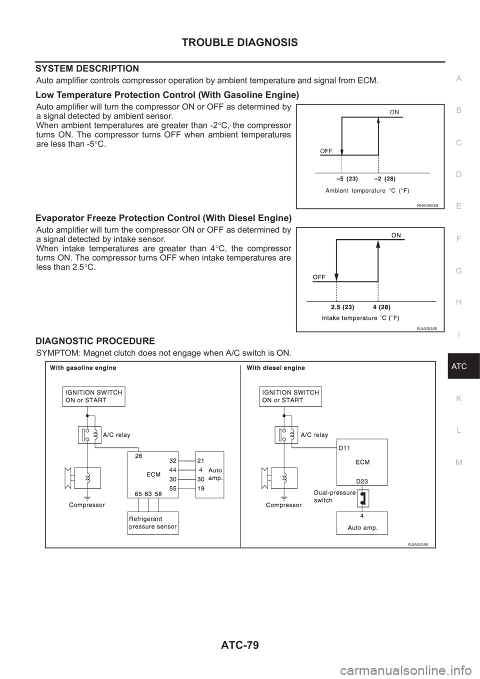
Auto amplifier controls compressor operation by ambient temperature and signal from ECM.
Low Temperature Protection Control (With Gasoline Engine)
Auto amplifier will turn the compressor ON or OFF as determined by
a signal detected by ambient sensor.
When ambient temperatures are greater than -2°C, the compressor
turns ON. The compressor turns OFF when ambient temperatures
are less than -5°C.
Evaporator Freeze Protection Control (With Diesel Engine)
Auto amplifier will turn the compressor ON or OFF as determined by
a signal detected by intake sensor.
When intake temperatures are greater than 4°C, the compressor
turns ON. The compressor turns OFF when intake temperatures are
less than 2.5°C.
DIAGNOSTIC PROCEDURE
SYMPTOM: Magnet clutch does not engage when A/C switch is ON.
RHA094GB
RJIA0534E
RJIA0535E
Page 3491 of 3833
LT-1
LIGHTING SYSTEM
K ELECTRICAL
CONTENTS
C
D
E
F
G
H
I
J
L
M
SECTION
A
B
LT
LIGHTING SYSTEM
PRECAUTION ............................................................ 3
Precautions for Supplemental Restraint System
(SRS) “AIR BAG” and “SEAT BELT PRE-TEN-
SIONER” .................................................................. 3
Precaution ................................................................ 3
Wiring Diagrams and Trouble Diagnosis .................. 3
HEADLAMP ................................................................ 4
System Description .................................................. 4
DESCRIPTION ...................................................... 4
LOW BEAM OPERATION ..................................... 4
HIGH BEAM OPERATION/FLASH-TO-PASS
OPERATION ......................................................... 4
Wiring Diagram — H/LAMP — ................................. 5
Trouble Diagnoses ................................................... 6
Aiming Adjustment ................................................... 6
LOW BEAM ........................................................... 7
Bulb Replacement .................................................... 8
HEAD LAMP ......................................................... 8
CLEARANCE LAMP ............................................. 8
Removal and Installation .......................................... 8
REMOVAL ............................................................. 8
INSTALLATION ..................................................... 8
HEADLAMP - DAYTIME LIGHT SYSTEM - ............... 9
System Description .................................................. 9
DESCRIPTION ...................................................... 9
HEADLAMP OPERATION (DAYTIME LIGHT
CANCEL OPERATION) ........................................ 9
DAYTIME LIGHT OPERATION ............................. 9
Schematic .............................................................. 10
Wiring Diagram -DTRL- ........................................... 11
Trouble Diagnoses ................................................. 14
DAYTIME LIGHT CONTROL UNIT INSPECTION
TABLE ................................................................. 14
Bulb Replacement .................................................. 14
Aiming Adjustment ................................................. 14
HEADLAMP AIMING CONTROL ............................. 15
Wiring Diagram -H/AIM- ......................................... 15
Removal and Installation ........................................ 16
Switch Circuit Inspection ........................................ 16
TURN SIGNAL AND HAZARD WARNING LAMPS ... 17System Description ................................................. 17
TURN SIGNAL OPERATION .............................. 17
HAZARD LAMP OPERATION ............................. 17
Wiring Diagram — TURN — ................................... 19
Trouble Diagnoses ................................................. 21
Electrical Components Inspection .......................... 21
COMBINATION FLASHER UNIT CHECK ........
... 21
Bulb Replacement .................................................. 22
FRONT TURN SIGNAL LAMP ............................ 22
SIDE TURN SIGNAL LAMP ................................ 22
REAR TURN SIGNAL LAMP .............................. 22
Removal and Installation for Front Turn Signal Lamp ... 22
REMOVAL ........................................................... 22
INSTALLATION ................................................... 22
Removal and Installation for Side Turn Signal Lamp ... 23
Removal and Installation for Rear Turn Signal Lamp ... 23
LIGHTING AND TURN SIGNAL SWITCH ................ 24
Removal and Installation ........................................ 24
Switch Circuit Inspection ........................................ 24
HAZARD SWITCH .................................................... 25
Removal and Installation ........................................ 25
REMOVAL ........................................................... 25
INSTALLATION ................................................... 25
STOP LAMP .............................................................. 26
Wiring Diagram — STOP/L — ................................ 26
Bulb Replacement .................................................. 27
STOP LAMP ........................................................ 27
HIGH-MOUNTED STOP LAMP ........................... 27
Removal and Installation ........................................ 27
STOP LAMP ........................................................ 27
HIGH-MOUNTED STOP LAMP ........................... 27
BACK-UP LAMP ....................................................... 28
Wiring Diagram — BACK/L — ................................ 28
Bulb Replacement .................................................. 29
Removal and Installation ........................................ 29
PARKING, LICENSE PLATE AND TAIL LAMPS ..... 30
Wiring Diagram — TAIL/L — .................................. 30
Bulb Replacement .................................................. 32
PARKING AND TAIL LAMPS .............................. 32
Page 3498 of 3833
LT-8
HEADLAMP
Bulb Replacement
EKS003CH
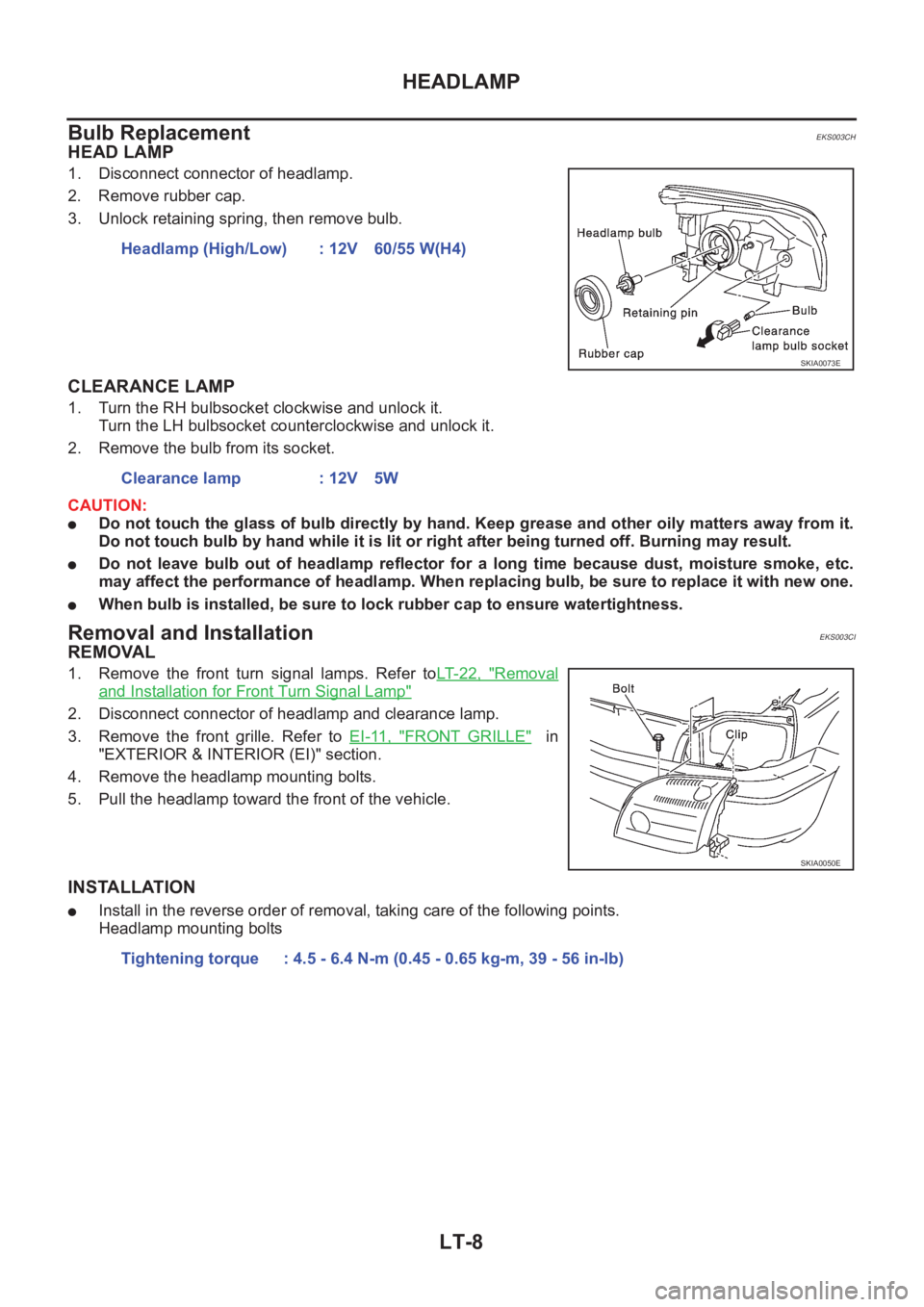
HEAD LAMP
1. Disconnect connector of headlamp.
2. Remove rubber cap.
3. Unlock retaining spring, then remove bulb.
CLEARANCE LAMP
1. Turn the RH bulbsocket clockwise and unlock it.
Turn the LH bulbsocket counterclockwise and unlock it.
2. Remove the bulb from its socket.
CAUTION:
●Do not touch the glass of bulb directly by hand. Keep grease and other oily matters away from it.
Do not touch bulb by hand while it is lit or right after being turned off. Burning may result.
●Do not leave bulb out of headlamp reflector for a long time because dust, moisture smoke, etc.
may affect the performance of headlamp. When replacing bulb, be sure to replace it with new one.
●When bulb is installed, be sure to lock rubber cap to ensure watertightness.
Removal and Installation EKS003CI
REMOVAL
1. Remove the front turn signal lamps. Refer toLT- 2 2 , "Removal
and Installation for Front Turn Signal Lamp"
2. Disconnect connector of headlamp and clearance lamp.
3. Remove the front grille. Refer to EI-11, "
FRONT GRILLE" in
"EXTERIOR & INTERIOR (EI)" section.
4. Remove the headlamp mounting bolts.
5. Pull the headlamp toward the front of the vehicle.
INSTALLATION
●Install in the reverse order of removal, taking care of the following points.
Headlamp mounting boltsHeadlamp (High/Low) : 12V 60/55 W(H4)
SKIA0073E
Clearance lamp : 12V 5W
SKIA0050E
Tightening torque : 4.5 - 6.4 N-m (0.45 - 0.65 kg-m, 39 - 56 in-lb)