Page 3533 of 3833
REAR COMBINATION LAMP
LT-43
C
D
E
F
G
H
I
J
L
MA
B
LT
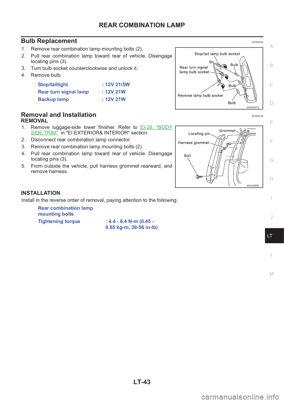
Bulb ReplacementEKS00164
1. Remove rear combination lamp mounting bolts (2).
2. Pull rear combination lamp toward rear of vehicle. Disengage
locating pins (3).
3. Turn bulb socket counterclockwise and unlock it.
4. Remove bulb.
Removal and InstallationEKS00165
REMOVAL
1. Remove luggage-side lower finisher. Refer to EI-26, "BODY
SIDE TRIM" in "EI EXTERIOR& INTERIOR" section.
2. Disconnect rear combination lamp connector.
3. Remove rear combination lamp mounting bolts (2).
4. Pull rear combination lamp toward rear of vehicle. Disengage
locating pins (3).
5. From outside the vehicle, pull harness grommet rearward, and
remove harness.
INSTALLATION
Install in the reverse order of removal, paying attention to the following. Stop/taillight : 12V 21/5W
Rear turn signal lamp : 12V 21W
Backup lamp : 12V 21W
SKIA0057E
SKIA0058E
Rear combination lamp
mounting bolts
Tightening torque : 4.4 - 6.4 N-m (0.45 -
0.65 kg-m, 39-56 in-lb)
Page 3534 of 3833
LT-44
COMBINATION SWITCH
COMBINATION SWITCH
PFP:25567
Removal and InstallationEKS001V6
Refer to SRS-33, "SPIRAL CABLE" in "SUPPLEMENTAL RESTRAINT SYSTEM (SRS)" section for details.
Switch Circuit InspectionEKS001V7
Refer to LT- 2 4 , "Switch Circuit Inspection" in "LIGHTING AND TURN SIGNAL SWITCH" section, and WW-7,
"Terminal and Reference Values for Combination Switch" , WW-15, "Terminal and Reference Values for Com-
bination Switch" in“ WW Wiper/Washer Horn” section for details.
Page 3546 of 3833
LT-56
INTERIOR ROOM LAMP
INTERIOR ROOM LAMP TIMER OPERATION
When interior room lamp switch is in the “DOOR” position, the time control unit keeps the interior room lamp
illuminated for about 30 seconds when:
●unlock signal is supplied from driver's door unlock sensor while all doors are closed and key is out of igni-
tion key cylinder
●key is removed from ignition key cylinder while all doors are closed
●driver's door is opened and then closed while key is out of the ignition key cylinder. (However, if the
driver's door is closed with the key inserted in the ignition key cylinder after the driver's door is opened
with the key removed, the timer is operated.)
The timer is canceled when:
●driver's door is locked,
●driver's door is opened, or
●ignition switch is turned ON.
ON-OFF CONTROL
When the driver side door, front passenger door, rear LH or RH door is opened, the interior room lamp turns
on while the interior room lamp switch is in the “DOOR” position.
Page 3557 of 3833
BULB SPECIFICATIONS
LT-67
C
D
E
F
G
H
I
J
L
MA
B
LT
BULB SPECIFICATIONSPFP:26297
HeadlampEKS003GS
Exterior LampEKS003GT
Interior Lamp/IlluminationEKS003GU
Item Wattage (W)
Low/High55 /60(H4)
Item Wattage (W)
Front combination lamp Clearance lamp 5
Front turn signal lamp21(amber)
Side turn signal lamp5
Fog lampFront fog lamp 55(H3)
Rear fog lamp 21
Rear combination lampStop/Tail lamp 21/5
Turn signal lamp 21
Back-up lamp 21
License plate lamp5
High-mounted stop lamp5
Item Wattage (W)
Interior room lamp10
Spot lampWithout sunroof 8
With sunroof 10
Luggage room lamp10
SMA for models with roof mounted driving lamp
Page 3562 of 3833
DI-4
COMBINATION METERS (LHD MODELS)
COMBINATION METERS (LHD MODELS)
PFP:24810
System DescriptionEKS002Z7
UNIFIED CONTROL METER
●Speedometer, odo/trip meter, tachometer, fuel gauge and water temperature gauge are controlled totally
by control unit built-in combination meter.
●Digital meter is adopted for odo/trip meter.*
*The record of the odo meter is kept even if the battery cable is disconnected. The record of the trip meter
is erased when the battery cable is disconnected.
●Odo/trip meter segment can be checked in diagnosis mode.
●Meter/gauge can be checked in diagnosis mode.
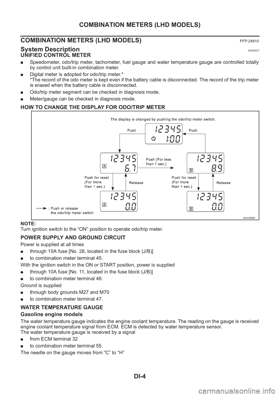
HOW TO CHANGE THE DISPLAY FOR ODO/TRIP METER
NOTE:
Turn ignition switch to the “ON” position to operate odo/trip meter.
POWER SUPPLY AND GROUND CIRCUIT
Power is supplied at all times
●through 10A fuse [No. 28, located in the fuse block (J/B)]
●to combination meter terminal 45.
With the ignition switch in the ON or START position, power is supplied
●through 10A fuse [No. 11, located in the fuse block (J/B)]
●to combination meter terminal 46.
Ground is supplied
●through body grounds M27 and M70
●to combination meter terminal 47.
WATER TEMPERATURE GAUGE
Gasoline engine models
The water temperature gauge indicates the engine coolant temperature. The reading on the gauge is received
engine coolant temperature signal from ECM. ECM is detected by water temperature sensor.
The water temperature gauge is received by a signal
●from ECM terminal 32
●to combination meter terminal 55.
The needle on the gauge moves from “C” to “H”
SKIA0896E
Page 3574 of 3833
DI-16
COMBINATION METERS (LHD MODELS)
Inspection/Vehicle speed signal
EKS002ZH
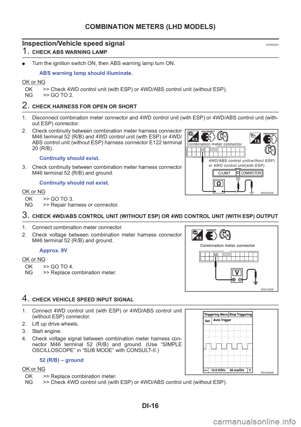
1. CHECK ABS WARNING LAMP
●Turn the ignition switch ON, then ABS warning lamp turn ON.
OK or NG
OK >> Check 4WD control unit (with ESP) or 4WD/ABS control unit (without ESP).
NG >> GO TO 2.
2. CHECK HARNESS FOR OPEN OR SHORT
1. Disconnect combination meter connector and 4WD control unit (with ESP) or 4WD/ABS control unit (with-
out ESP) connector.
2. Check continuity between combination meter harness connector
M46 terminal 52 (R/B) and 4WD control unit (with ESP) or 4WD/
ABS control unit (without ESP) harness connector E122 terminal
20 (R/B).
3. Check continuity between combination meter harness connector
M46 terminal 52 (R/B) and ground.
OK or NG
OK >> GO TO 3.
NG >> Repair harness or connector.
3. CHECK 4WD/ABS CONTROL UNIT (WITHOUT ESP) OR 4WD CONTROL UNIT (WITH ESP) OUTPUT
1. Connect combination meter connector.
2. Check voltage between combination meter harness connector
M46 terminal 52 (R/B) and ground.
OK or NG
OK >> GO TO 4.
NG >> Replace combination meter.
4. CHECK VEHICLE SPEED INPUT SIGNAL
1. Connect 4WD control unit (with ESP) or 4WD/ABS control unit
(without ESP) connector.
2. Lift up drive wheels.
3. Start engine.
4. Check voltage signal between combination meter harness con-
nector M46 terminal 52 (R/B) and ground. (Use “SIMPLE
OSCILLOSCOPE” in “SUB MODE” with CONSULT-II.)
OK or NG
OK >> Replace combination meter.
NG >> Check 4WD control unit (with ESP) or 4WD/ABS control unit (without ESP). ABS warning lamp should illuminate.
Continuity should exist.
Continuity should not exist.
SKIA4423E
Approx. 9V
SKIA1004E
52 (R/B) – ground
SKIA0990E
Page 3582 of 3833
DI-24
COMBINATION METERS (RHD MODELS)
COMBINATION METERS (RHD MODELS)
PFP:24810
System DescriptionEKS0030H
UNIFIED CONTROL METER
●Speedometer, odo/trip meter, tachometer, fuel gauge and water temperature gauge are controlled totally
by control unit built-in combination meter.
●Digital meter is adopted for odo/trip meter.*
*The record of the odo meter is kept even if the battery cable is disconnected. The record of the trip meter
is erased when the battery cable is disconnected.
●Odo/trip meter segment can be checked in diagnosis mode.
●Meter/gauge can be checked in diagnosis mode.
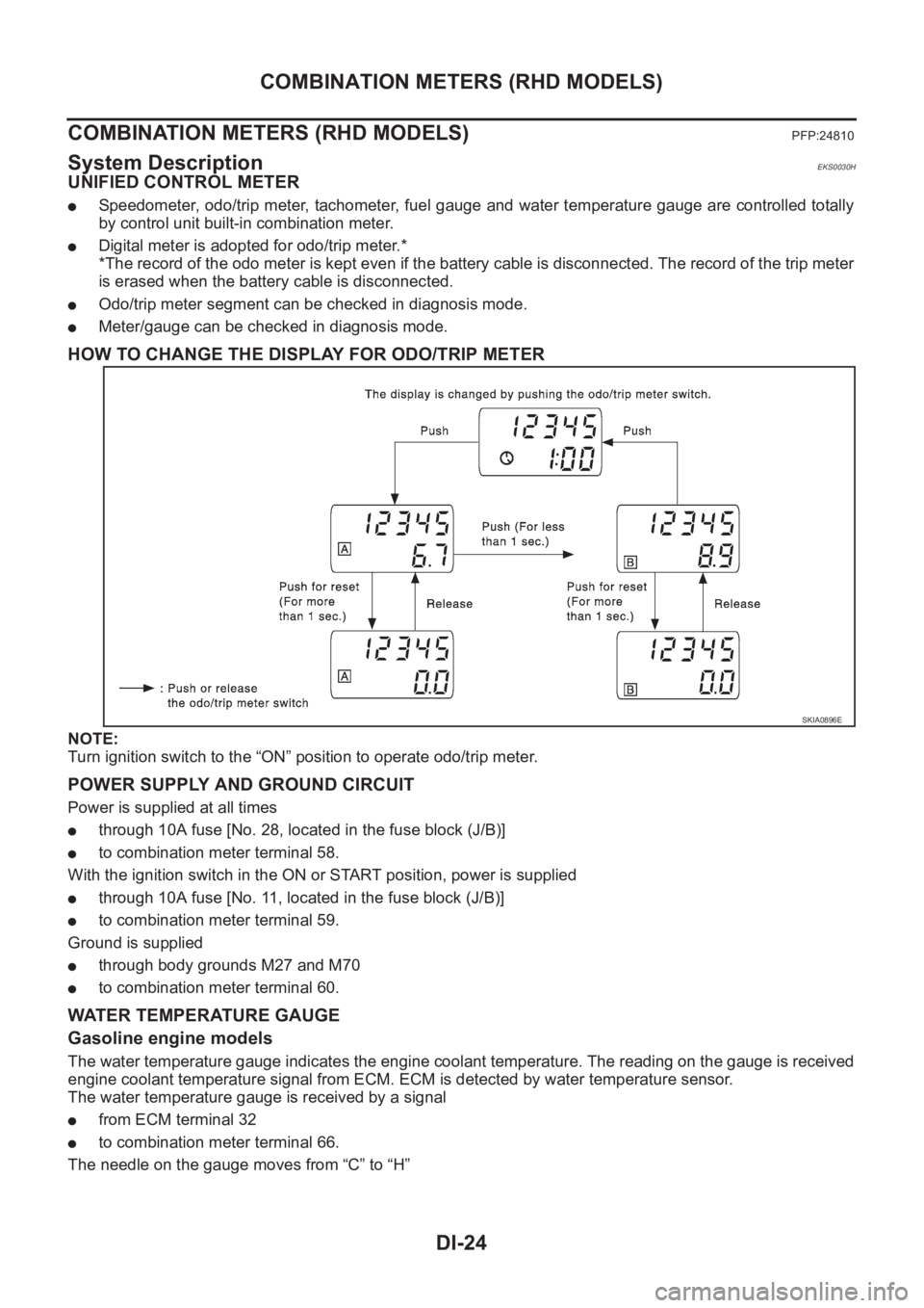
HOW TO CHANGE THE DISPLAY FOR ODO/TRIP METER
NOTE:
Turn ignition switch to the “ON” position to operate odo/trip meter.
POWER SUPPLY AND GROUND CIRCUIT
Power is supplied at all times
●through 10A fuse [No. 28, located in the fuse block (J/B)]
●to combination meter terminal 58.
With the ignition switch in the ON or START position, power is supplied
●through 10A fuse [No. 11, located in the fuse block (J/B)]
●to combination meter terminal 59.
Ground is supplied
●through body grounds M27 and M70
●to combination meter terminal 60.
WATER TEMPERATURE GAUGE
Gasoline engine models
The water temperature gauge indicates the engine coolant temperature. The reading on the gauge is received
engine coolant temperature signal from ECM. ECM is detected by water temperature sensor.
The water temperature gauge is received by a signal
●from ECM terminal 32
●to combination meter terminal 66.
The needle on the gauge moves from “C” to “H”
SKIA0896E
Page 3593 of 3833
COMBINATION METERS (RHD MODELS)
DI-35
C
D
E
F
G
H
I
J
L
MA
B
DI
Inspection/Water Temperature Gauge/Diesel Engine ModelsEKS0030R
1.CHECK THERMAL TRANSMITTER
Refer to DI-42, "
THERMAL TRANSMITTER CHECK" .
OK or NG
OK >> GO TO 2.
NG >> Replace thermal transmitter.
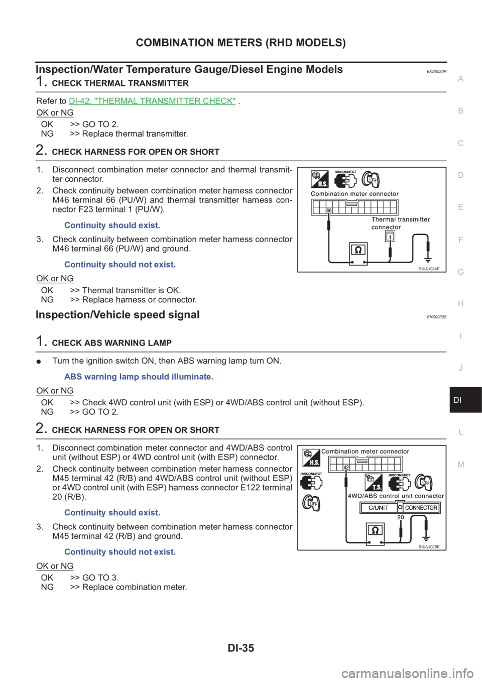
2.CHECK HARNESS FOR OPEN OR SHORT
1. Disconnect combination meter connector and thermal transmit-
ter connector.
2. Check continuity between combination meter harness connector
M46 terminal 66 (PU/W) and thermal transmitter harness con-
nector F23 terminal 1 (PU/W).
3. Check continuity between combination meter harness connector
M46 terminal 66 (PU/W) and ground.
OK or NG
OK >> Thermal transmitter is OK.
NG >> Replace harness or connector.
Inspection/Vehicle speed signalEKS0030S
1.CHECK ABS WARNING LAMP
●Turn the ignition switch ON, then ABS warning lamp turn ON.
OK or NG
OK >> Check 4WD control unit (with ESP) or 4WD/ABS control unit (without ESP).
NG >> GO TO 2.
2.CHECK HARNESS FOR OPEN OR SHORT
1. Disconnect combination meter connector and 4WD/ABS control
unit (without ESP) or 4WD control unit (with ESP) connector.
2. Check continuity between combination meter harness connector
M45 terminal 42 (R/B) and 4WD/ABS control unit (without ESP)
or 4WD control unit (with ESP) harness connector E122 terminal
20 (R/B).
3. Check continuity between combination meter harness connector
M45 terminal 42 (R/B) and ground.
OK or NG
OK >> GO TO 3.
NG >> Replace combination meter.Continuity should exist.
Continuity should not exist.
SKIA1024E
ABS warning lamp should illuminate.
Continuity should exist.
Continuity should not exist.
SKIA1025E