2001 NISSAN X-TRAIL turn signal
[x] Cancel search: turn signalPage 3635 of 3833

FRONT WIPER AND WASHER SYSTEM
WW-7
C
D
E
F
G
H
I
J
L
MA
B
WW
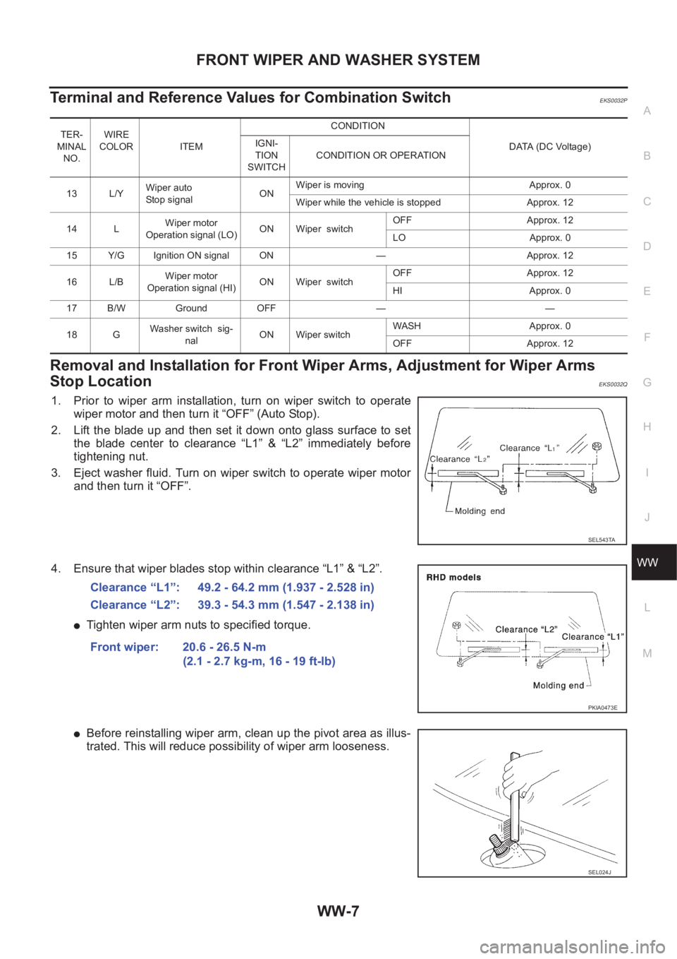
Terminal and Reference Values for Combination SwitchEKS0032P
Removal and Installation for Front Wiper Arms, Adjustment for Wiper Arms
Stop Location
EKS0032Q
1. Prior to wiper arm installation, turn on wiper switch to operate
wiper motor and then turn it “OFF” (Auto Stop).
2. Lift the blade up and then set it down onto glass surface to set
the blade center to clearance “L1” & “L2” immediately before
tightening nut.
3. Eject washer fluid. Turn on wiper switch to operate wiper motor
and then turn it “OFF”.
4. Ensure that wiper blades stop within clearance “L1” & “L2”.
●Tighten wiper arm nuts to specified torque.
●Before reinstalling wiper arm, clean up the pivot area as illus-
trated. This will reduce possibility of wiper arm looseness.
TER-
MINAL
NO.WIRE
COLOR ITEM CONDITION
DATA (DC Voltage) IGNI-
TION
SWITCHCONDITION OR OPERATION
13 L/YWiper auto
Stop signalONWiper is moving Approx. 0
Wiper while the vehicle is stopped Approx. 12
14 LWiper motor
Operation signal (LO)ON Wiper switchOFF Approx. 12
LO Approx. 0
15 Y/G Ignition ON signal ON — Approx. 12
16 L/BWiper motor
Operation signal (HI)ON Wiper switchOFF Approx. 12
HI Approx. 0
17 B/W Ground OFF — —
18 GWasher switch sig-
nalON Wiper switchWASH Approx. 0
OFF Approx. 12
SEL543TA
Clearance “L1”: 49.2 - 64.2 mm (1.937 - 2.528 in)
Clearance “L2”: 39.3 - 54.3 mm (1.547 - 2.138 in)
Front wiper: 20.6 - 26.5 N-m
(2.1 - 2.7 kg-m, 16 - 19 ft-lb)
PKIA0473E
SEL024J
Page 3643 of 3833

REAR WIPER AND WASHER SYSTEM
WW-15
C
D
E
F
G
H
I
J
L
MA
B
WW
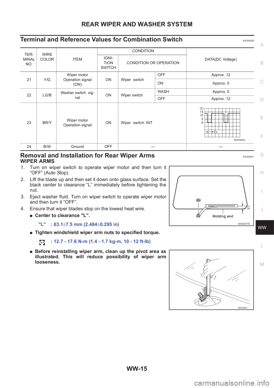
Terminal and Reference Values for Combination SwitchEKS00330
Removal and Installation for Rear Wiper Arms EKS00331
WIPER ARMS
1. Turn on wiper switch to operate wiper motor and then turn it
“OFF” (Auto Stop).
2. Lift the blade up and then set it down onto glass surface. Set the
black center to clearance “L” immediately before tightening the
nut.
3. Eject washer fluid. Turn on wiper switch to operate wiper motor
and then turn it “OFF”.
4. Ensure that wiper blades stop on the lowest heat wire.
●Center to clearance "L".
●Tighten windshield wiper arm nuts to specified torque.
●Before reinstalling wiper arm, clean up the pivot area as
illustrated. This will reduce possibility of wiper arm
looseness.
TER-
MINAL
NO.WIRE
COLOR ITEM CONDITION
DATA(DC Voltage) IGNI-
TION
SWITCHCONDITION OR OPERATION
21 Y/GWiper motor
Operation signal
(ON)ON Wiper switchOFF Approx. 12
ON Approx. 0
22 LG/BWasher switch sig-
nalON Wiper switchWASH Approx. 0
OFF Approx. 12
23 BR/YWiper motor
Operation signalON Wiper switch: INT
24 B/W Ground OFF — —
SKIA0083J
"L" : 63.1±7.5 mm (2.484±0.295 in)
: 12.7 - 17.6 N-m (1.4 - 1.7 kg-m, 10 - 12 ft-lb)SKIA0077E
SEL024J
Page 3766 of 3833

PG-62
HARNESS
R/FOG LT Rear Fog Lamp
ROOM/L LT Interior Room Lamp
RP/SEN EC Refrigerant Pressure Sensor
RRO2 EC Heated Oxygen Sensor 2 (Rear)
RRO2/H EC Heated Oxygen Sensor 2 Heater (Rear)
S/LOCK BL Super Lock
S/SIG EC Start Signal
S/WARN SB Seat Belt Warning System
SCTC/V EC Suction Control Valve
SHIFT AT A/T Shift Lock System
SROOF BL Sunroof
SRS SRS Supplemental Restraint System (SRS)
SSV/A AT Shift Solenoid Valve A
SSV/B AT Shift Solenoid Valve B
START SC Starting System
STOP/L LT Stop Lamp
T/MTR EC Throttle Control Motor
TAIL/L LT Parking, License and Tail Lamps
TCV AT Torque Converter Clutch Solenoid Valve
TM/RLY EC Throttle Control Motor Relay
TPS EC, AT Throttle Position Sensor
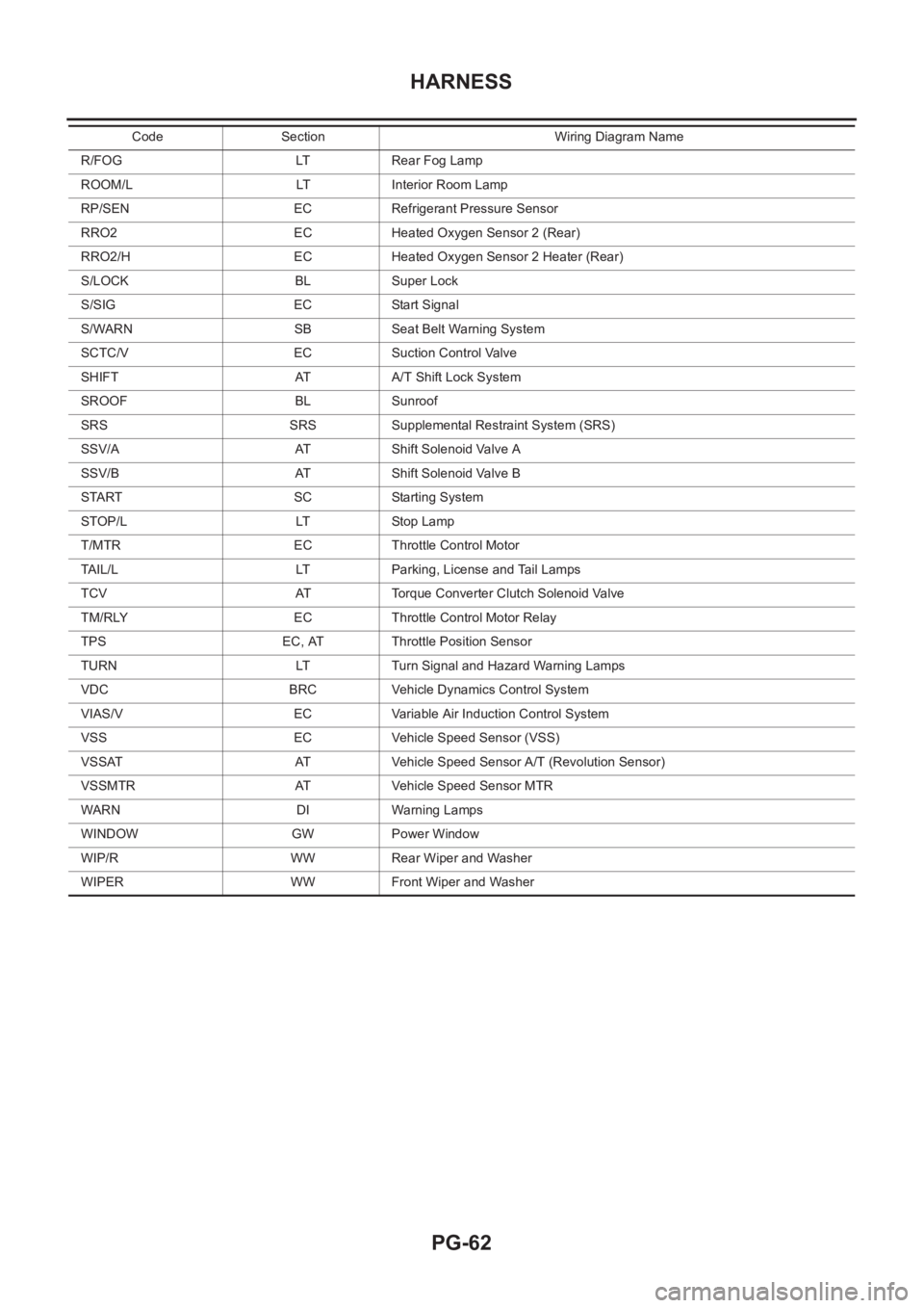
TURN LT Turn Signal and Hazard Warning Lamps
VDC BRC Vehicle Dynamics Control System
VIAS/V EC Variable Air Induction Control System
VSS EC Vehicle Speed Sensor (VSS)
VSSAT AT Vehicle Speed Sensor A/T (Revolution Sensor)
VSSMTR AT Vehicle Speed Sensor MTR
WARN DI Warning Lamps
WINDOW GW Power Window
WIP/R WW Rear Wiper and Washer
WIPER WW Front Wiper and WasherCode Section Wiring Diagram Name
Page 3786 of 3833

MA-6
GENERAL MAINTENANCE
GENERAL MAINTENANCE
PFP:00000
General MaintenanceELS000AL
General maintenance includes those items which should be checked during the normal day-to-day operation
of the vehicle. They are essential if the vehicle is to continue operating properly. The owners can perform the
checks and inspections themselves or they can have their NISSAN dealers do them for a nominal charge.
OUTSIDE THE VEHICLE
The maintenance items listed here should be performed from time to time, unless otherwise specified.
INSIDE THE VEHICLE
The maintenance items listed here should be checked on a regular basis, such as when performing periodic maintenance, cleaning the
vehicle, etc.
UNDER THE HOOD AND VEHICLE
The maintenance items listed here should be checked periodically e.g. each time you check the engine oil or refuel. Item Reference page
TiresCheck the pressure with a gauge periodically when at a service station, includ-
ing the spare, and adjust to the specified pressure if necessary. Check carefully
for damage, cuts or excessive wear.—
Windshield wiper
bladesCheck for cracks or wear if not functioning correctly. —
Doors and engine
hoodCheck that all doors, the engine hood, the trunk lid and back door operate prop-
erly. Also ensure that all latches lock securely. Lubricate if necessary. Make sure
that the secondary latch keeps the hood from opening when the primary latch is
released.
When driving in areas using road salt or other corrosive materials, check for
lubrication frequently.BL-4
,BL-8
Tire rotationTires should be rotated every 5,000 km (3,000 miles).MA-38
Item Reference page
LampsMake sure that the headlamps, stop lamps, tail lamps, turn signal lamps, and
other lamps are all operating properly and installed securely. Also check head-
lamp aim.—
Warning lamps and
chimesMake sure that all warning lamps and buzzers/chimes are operating properly. —
Steering wheelCheck that it has the specified play.
Check for changes in the steering conditions, such as excessive free play, hard
steering or strange noises.
Free play: Less than 35 mm (1.38 in)—
Seat beltsCheck that all parts of the seat belt system (e.g. buckles, anchors, a dju sters and
retractors) operate properly and smoothly, and are installed securely. Check the
belt webbing for cuts, fraying, wear or damage.SB-3
Item Reference page
Windshield washer
fluidCheck that there is adequate fluid in the tank. —
Engine coolant levelCheck the coolant level when the engine is cold.CO-29
(QR20DE,
QR25DE)
CO-29
(YD22DDTi)
Engine oil levelCheck the level after parking the vehicle (on level ground) and turning off the
engine.LU-18
(QR20DE,
QR25DE)
LU-18
(YD22DDTi)
Brake and clutch fluid
levelsMake sure that the brake and clutch fluid levels are between the “MAX” and
“MIN” lines on the reservoir.MA-35
,MA-39
BatteryCheck the fluid level in each cell. It should be between the “MAX” and “MIN”
lines.—
Page 3833 of 3833

IDX-9
A
C
D
E
F
G
H
I
J
K
L B
IDX
ALPHABETICAL INDEX
Throwout bearing - See Clutch release bearing CL-13
Time control system .......................................... BCS-3
Timing chain(QR20DE•QR25DE) ...................... EM-37
Timing chain(YD22DDTi) .................. EM-167,EM-172
TM/RLY - Wiring diagram .............. EC-1020,EC-1283
Torque converter installation .............. AT-419,AT-514
TPS - Wiring diagram ...................... EC-889,EC-1218
TPS1 - Wiring diagram ...................... EC-214,EC-543
TPS2 - Wiring diagram ...................... EC-156,EC-530
TPS3 - Wiring diagram ...................... EC-369,EC-647
Transfer control unit inspection table ...... TF-42,TF-49
Transmission case (M/T) ...................... MT-17,MT-22
Trouble diagnoses ................................................ GI-9
Turbocharger charge air cooler(YD22DDTi) .... EM-122
Turbocharger precautions .................................... GI-6
Turbocharger(YD22DDTi) ............................... EM-127
TURN - Wiring diagram .......................... LT-17,LT-19
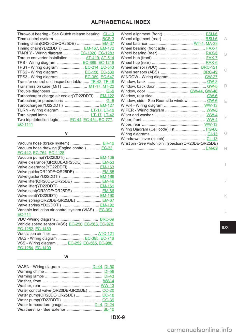
Turn signal lamp ..................................... LT-17,LT-42
Two trip detection logic ......... EC-44,EC-454,EC-777,
EC-1141
V
Vacuum hose (brake system) ............................ BR-19
Vacuum hose drawing (Engine control) ............ EC-32,
EC-442
,EC-764,EC-1128
Vacuum pump(YD22DDTi) .............................. EM-139
Valve clearance(QR20DE•QR25DE) ................. EM-53
Valve clearance(YD22DDTi) ........................... EM-163
Valve guide(QR20DE•QR25DE) ....................... EM-65
Valve guide(YD22DDTi) .................................. EM-189
Valve lifter(QR20DE•QR25DE) ......................... EM-46
Valve lifter(YD22DDTi) .................................... EM-161
Valve seat(QR20DE•QR25DE) ......................... EM-66
Valve seat(YD22DDTi) .................................... EM-190
Valve spring(QR20DE•QR25DE) ...................... EM-67
Valve spring(YD22DDTi) ................................. EM-192
Variable induction air control system (VIAS) .. EC-393,
EC-714
VDC -Wiring diagram ...................................... BRC-69
Vehicle speed sensor (VSS) EC-250,EC-563,EC-978,
EC-1252
,EC-1489
Ventilation air filter ......................................... ATC-121
VIAS - Wiring diagram ....................... EC-395,EC-716
VSS - Wiring diagram ......... EC-252,EC-565,EC-980,
EC-1254
,EC-1490
W
WARN - Wiring diagram ........................... DI-44
,DI-50
Warning chime .................................................... DI-58
Warning lamps .................................................... DI-43
Washer, front ..................................................... WW-4
Washer, rear .................................................... WW-13
Water control valve(QR20DE•QR25DE) ........... CO-20
Water pump(QR20DE•QR25DE) ....................... CO-18
Water pump(YD22DDTi) ................................... CO-39
Water temperature gauge ........................... DI-4,DI-24
Weatherstrip - See Exterior ................................ BL-10
Wheel alignment (front) ..................................... FSU-6
Wheel alignment (rear) ..................................... RSU-6
Wheel balance ........................................ WT-4,MA-38
Wheel bearing (front axle) ................................. FAX-7
Wheel bearing (rear) ......................................... RAX-6
Wheel hub (front) ............................................... FAX-7
Wheel hub (rear) ............................................... RAX-6
Wheel sensor (VDC) ..................................... BRC-121
Wheel sensors (ABS) ..................................... BRC-49
WINDOW - Wiring diagram ............................... GW-27
Window, back ..................................................... GW-8
Window, back door ............................................. GW-8
Window, door ...................................... GW-44,GW-46
Window, rear side ............................................... GW-6
Window, side - See Rear side window ............... GW-6
WIP/R - Wiring diagram ................................... WW-13
WIPER - Wiring diagram .................................... WW-6
Wiper and washer .............................................. WW-4
Wiper, front ........................................................ WW-4
Wiper, rear ....................................................... WW-13
Wiring Diagram (Cell code) list .......................... PG-60
Wiring diagrams .................................................. GI-13
Withdrawal lever (clutch) ................................... CL-13
Wrist pin - See Piston pin inspection(QR20DE•QR25DE)
...........................................................................EM-89