Page 3113 of 3833
MULTI-REMOTE CONTROL SYSTEM
BL-61
C
D
E
F
G
H
J
K
L
MA
B
BL
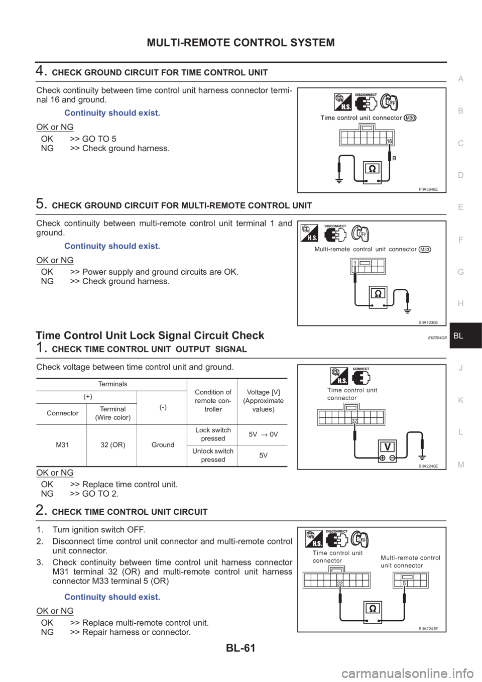
4.CHECK GROUND CIRCUIT FOR TIME CONTROL UNIT
Check continuity between time control unit harness connector termi-
nal 16 and ground.
OK or NG
OK >> GO TO 5
NG >> Check ground harness.
5.CHECK GROUND CIRCUIT FOR MULTI-REMOTE CONTROL UNIT
Check continuity between multi-remote control unit terminal 1 and
ground.
OK or NG
OK >> Power supply and ground circuits are OK.
NG >> Check ground harness.
Time Control Unit Lock Signal Circuit CheckEIS004G8
1.CHECK TIME CONTROL UNIT OUTPUT SIGNAL
Check voltage between time control unit and ground.
OK or NG
OK >> Replace time control unit.
NG >> GO TO 2.
2.CHECK TIME CONTROL UNIT CIRCUIT
1. Turn ignition switch OFF.
2. Disconnect time control unit connector and multi-remote control
unit connector.
3. Check continuity between time control unit harness connector
M31 terminal 32 (OR) and multi-remote control unit harness
connector M33 terminal 5 (OR)
OK or NG
OK >> Replace multi-remote control unit.
NG >> Repair harness or connector.Continuity should exist.
PIIA3646E
Continuity should exist.
SIIA1230E
Terminals
Condition of
remote con-
trollerVoltage [V]
(Approximate
values) (+)
(-)
ConnectorTerminal
(Wire color)
M31 32 (OR) GroundLock switch
pressed5V → 0V
Unlock switch
pressed5V
SIIA2240E
Continuity should exist.
SIIA2241E
Page 3114 of 3833
BL-62
MULTI-REMOTE CONTROL SYSTEM
Time Control Unit Unlock Signal Circuit Check
EIS004G9
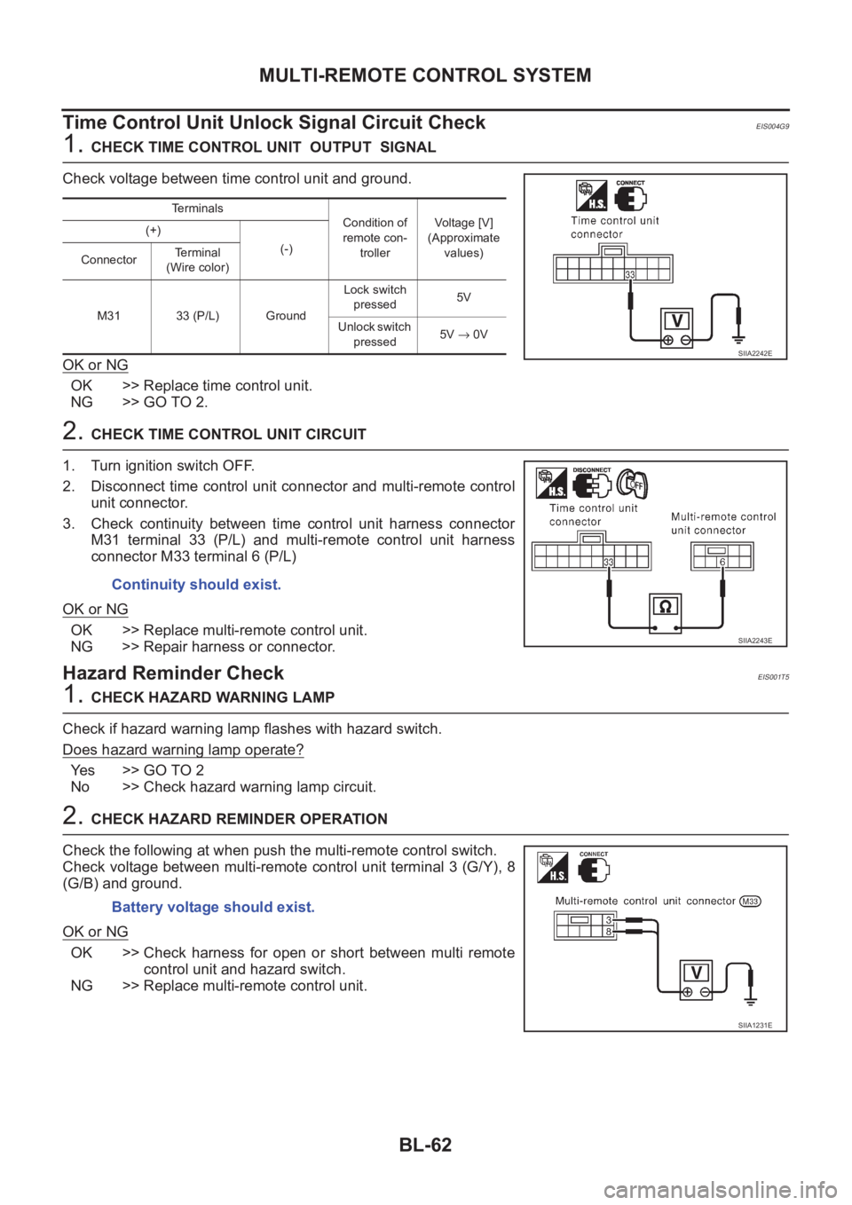
1. CHECK TIME CONTROL UNIT OUTPUT SIGNAL
Check voltage between time control unit and ground.
OK or NG
OK >> Replace time control unit.
NG >> GO TO 2.
2. CHECK TIME CONTROL UNIT CIRCUIT
1. Turn ignition switch OFF.
2. Disconnect time control unit connector and multi-remote control
unit connector.
3. Check continuity between time control unit harness connector
M31 terminal 33 (P/L) and multi-remote control unit harness
connector M33 terminal 6 (P/L)
OK or NG
OK >> Replace multi-remote control unit.
NG >> Repair harness or connector.
Hazard Reminder CheckEIS001T5
1. CHECK HAZARD WARNING LAMP
Check if hazard warning lamp flashes with hazard switch.
Does hazard warning lamp operate?
Yes >> GO TO 2
No >> Check hazard warning lamp circuit.
2. CHECK HAZARD REMINDER OPERATION
Check the following at when push the multi-remote control switch.
Check voltage between multi-remote control unit terminal 3 (G/Y), 8
(G/B) and ground.
OK or NG
OK >> Check harness for open or short between multi remote
control unit and hazard switch.
NG >> Replace multi-remote control unit.
Terminals
Condition of
remote con-
trollerVoltage [V]
(Approximate
values) (+)
(-)
ConnectorTerminal
(Wire color)
M31 33 (P/L) GroundLock switch
pressed5V
Unlock switch
pressed5V → 0V
SIIA2242E
Continuity should exist.
SIIA2243E
Battery voltage should exist.
SIIA1231E
Page 3144 of 3833
BL-92
NATS (NISSAN ANTI-THEFT SYSTEM)
3. CHECK IGN SW. ON SIGNAL
1. Turn ignition switch ON.
2. Check voltage between terminal 7 of IMMU and ground with CONSULT-II or tester.
OK or NG
OK >> GO TO 4
NG >> Check the following
●10A fuse [No. 5, located in the fuse block (J/B)]
●Harness for open or short between fuse and IMMU
connector
Ref. part No. C2
4. CHECK GROUND CIRCUIT FOR IMMU
1. Turn ignition OFF.
2. Check harness continuity between IMMU terminal 4 and ground.
OK or NG
OK >> GO TO 5
NG >> Repair harness. Ref. part No. C3
5. CHECK COMMUNICATION LINE OPEN CIRCUIT
1. Disconnect ECM connector.
2. Check harness continuity between ECM terminal 31 (Gasoline engine) or E20 (Diesel engine) and IMMU
terminal 1.
OK or NG
OK >> GO TO 6
NG >>
●Repair harness or connector.
●Ref. part No. C4 Battery voltage should exist.
SIIA1235E
Continuity should exist.
SIIA1237E
Continuity should exist.
SIIA1238E
Page 3145 of 3833
NATS (NISSAN ANTI-THEFT SYSTEM)
BL-93
C
D
E
F
G
H
J
K
L
MA
B
BL
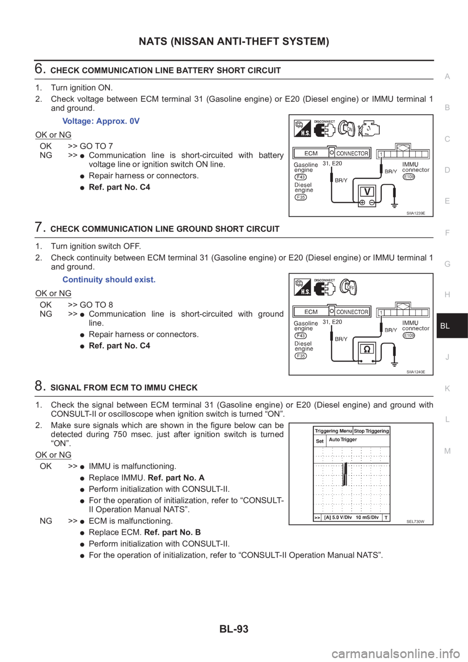
6.CHECK COMMUNICATION LINE BATTERY SHORT CIRCUIT
1. Turn ignition ON.
2. Check voltage between ECM terminal 31 (Gasoline engine) or E20 (Diesel engine) or IMMU terminal 1
and ground.
OK or NG
OK >> GO TO 7
NG >>
●Communication line is short-circuited with battery
voltage line or ignition switch ON line.
●Repair harness or connectors.
●Ref. part No. C4
7.CHECK COMMUNICATION LINE GROUND SHORT CIRCUIT
1. Turn ignition switch OFF.
2. Check continuity between ECM terminal 31 (Gasoline engine) or E20 (Diesel engine) or IMMU terminal 1
and ground.
OK or NG
OK >> GO TO 8
NG >>
●Communication line is short-circuited with ground
line.
●Repair harness or connectors.
●Ref. part No. C4
8.SIGNAL FROM ECM TO IMMU CHECK
1. Check the signal between ECM terminal 31 (Gasoline engine) or E20 (Diesel engine) and ground with
CONSULT-II or oscilloscope when ignition switch is turned “ON”.
2. Make sure signals which are shown in the figure below can be
detected during 750 msec. just after ignition switch is turned
“ON”.
OK or NG
OK >>●IMMU is malfunctioning.
●Replace IMMU. Ref. part No. A
●Perform initialization with CONSULT-II.
●For the operation of initialization, refer to “CONSULT-
II Operation Manual NATS”.
NG >>
●ECM is malfunctioning.
●Replace ECM. Ref. part No. B
●Perform initialization with CONSULT-II.
●For the operation of initialization, refer to “CONSULT-II Operation Manual NATS”. Voltage: Approx. 0V
SIIA1239E
Continuity should exist.
SIIA1240E
SEL730W
Page 3170 of 3833
GW-18
REAR WINDOW DEFOGGER
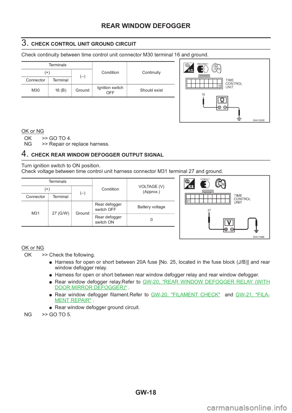
3. CHECK CONTROL UNIT GROUND CIRCUIT
Check continuity between time control unit connector M30 terminal 16 and ground.
OK or NG
OK >> GO TO 4.
NG >> Repair or replace harness.
4. CHECK REAR WINDOW DEFOGGER OUTPUT SIGNAL
Turn ignition switch to ON position.
Check voltage between time control unit harness connector M31 terminal 27 and ground.
OK or NG
OK >> Check the following.
●Harness for open or short between 20A fuse [No. 25, located in the fuse block (J/B)] and rear
window defogger relay.
●Harness for open or short between rear window defogger relay and rear window defogger.
●Rear window defogger relay.Refer to GW-20, "REAR WINDOW DEFOGGER RELAY (WITH
DOOR MIRROR DEFOGGER)" .
●Rear window defogger filament.Refer to GW-20, "FILAMENT CHECK" and GW-21, "FILA-
MENT REPAIR" .
●Rear window defogger ground circuit.
NG >> GO TO 5.
Te r m i n a l s
Condition Continuity (+)
(–)
Connector Terminal
M30 16 (B) GroundIgnition switch
OFFShould exist
SIIA1202E
Te r m i n a l s
ConditionVOLTAGE (V)
(Approx.) (+)
(–)
Connector Terminal
M31 27 (G/W) GroundRear defogger
switch OFFBattery voltage
Rear defogger
switch ON0
SIIA1198E
Page 3171 of 3833
REAR WINDOW DEFOGGER
GW-19
C
D
E
F
G
H
J
K
L
MA
B
GW
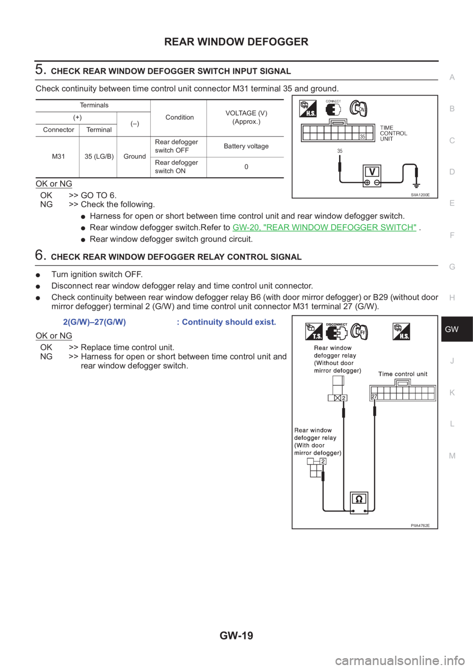
5.CHECK REAR WINDOW DEFOGGER SWITCH INPUT SIGNAL
Check continuity between time control unit connector M31 terminal 35 and ground.
OK or NG
OK >> GO TO 6.
NG >> Check the following.
●Harness for open or short between time control unit and rear window defogger switch.
●Rear window defogger switch.Refer to GW-20, "REAR WINDOW DEFOGGER SWITCH" .
●Rear window defogger switch ground circuit.
6.CHECK REAR WINDOW DEFOGGER RELAY CONTROL SIGNAL
●Turn ignition switch OFF.
●Disconnect rear window defogger relay and time control unit connector.
●Check continuity between rear window defogger relay B6 (with door mirror defogger) or B29 (without door
mirror defogger) terminal 2 (G/W) and time control unit connector M31 terminal 27 (G/W).
OK or NG
OK >> Replace time control unit.
NG >> Harness for open or short between time control unit and
rear window defogger switch.
Terminals
ConditionVOLTAGE (V)
(Approx.) (+)
(–)
Connector Terminal
M31 35 (LG/B) GroundRear defogger
switch OFFBattery voltage
Rear defogger
switch ON0
SIIA1200E
2(G/W)–27(G/W) : Continuity should exist.
PIIA4762E
Page 3177 of 3833
POWER WINDOW SYSTEM
GW-25
C
D
E
F
G
H
J
K
L
MA
B
GW
AUTO OPERATION
The power window AUTO feature enables the driver to open or close the driver's window without holding the
window switch in the down or up position.
The AUTO feature operates on the driver's window.
POWER WINDOW LOCK
The power window lock is designed to lock operation of all windows except for driver's window.
When the lock switch is pressed to lock position, ground of the sub–switches in the power window main switch
is disconnected.This prevents the power window motors from operating.
TIMER FUNCTION
With the timer function, driver power window can be operated for approximately 15 minutes after ignition
switch is turned OFF (positions other than ON). However, the timer will be cancel when a specific signal, such
as driver door close (door switch OFF) → open (door switch ON), or ignition switch OFF → ON, is input.
DRIVER WINDOW ANTI–PINCH FUNCTION
During raising operation of driver power window, if power window main switch detects that foreign object is
pinched, power window lowers approximately 150 mm (5.91 in).
NOTE:
Depending on environment and driving conditions, if a similar impact or load is applied to power window, it
may lower.
Operation conditions
●Driver door window is between fully-open and just before fully-closed position (when the limit switch is
ON).
●During automatic operation when ignition switch is turned ON.
●During automatic or manual operation when ignition switch is other than ON position (when the timer
operates).
Page 3303 of 3833
AIR CONDITIONER CONTROL
ATC-27
C
D
E
F
G
H
I
K
L
MA
B
AT C
AIR CONDITIONER CONTROLPFP:27500
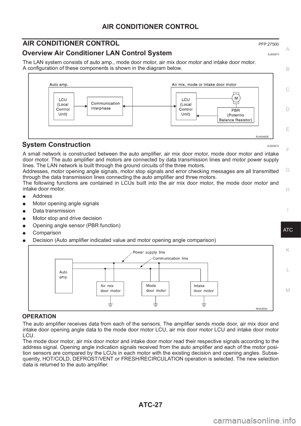
Overview Air Conditioner LAN Control SystemEJS000TI
The LAN system consists of auto amp., mode door motor, air mix door motor and intake door motor.
A configuration of these components is shown in the diagram below.
System ConstructionEJS000TJ
A small network is constructed between the auto amplifier, air mix door motor, mode door motor and intake
door motor. The auto amplifier and motors are connected by data transmission lines and motor power supply
lines. The LAN network is built through the ground circuits of the three motors.
Addresses, motor opening angle signals, motor stop signals and error checking messages are all transmitted
through the data transmission lines connecting the auto amplifier and three motors.
The following functions are contained in LCUs built into the air mix door motor, the mode door motor and
intake door motor.
●Address
●Motor opening angle signals
●Data transmission
●Motor stop and drive decision
●Opening angle sensor (PBR function)
●Comparison
●Decision (Auto amplifier indicated value and motor opening angle comparison)
OPERATION
The auto amplifier receives data from each of the sensors. The amplifier sends mode door, air mix door and
intake door opening angle data to the mode door motor LCU, air mix door motor LCU and intake door motor
LCU.
The mode door motor, air mix door motor and intake door motor read their respective signals according to the
address signal. Opening angle indication signals received from the auto amplifier and each of the motor posi-
tion sensors are compared by the LCUs in each motor with the existing decision and opening angles. Subse-
quently, HOT/COLD, DEFROST/VENT or FRESH/RECIRCULATION operation is selected. The new selection
data is returned to the auto amplifier.
RJIA0480E
RHA350H