Page 2996 of 3833

SB-14
SEAT BELT WARNING SYSTEM
Seat Belt Buckle Switch Inspection (Driver side)
EHS000GW
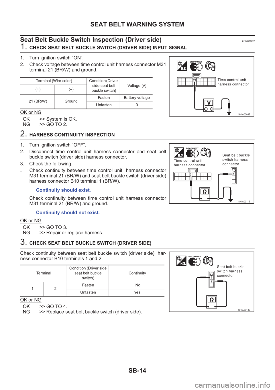
1. CHECK SEAT BELT BUCKLE SWITCH (DRIVER SIDE) INPUT SIGNAL
1. Turn ignition switch “ON”.
2. Check voltage between time control unit harness connector M31
terminal 21 (BR/W) and ground.
OK or NG
OK >> System is OK.
NG >> GO TO 2.
2. HARNESS CONTINUITY INSPECTION
1. Turn ignition switch “OFF”.
2. Disconnect time control unit harness connector and seat belt
buckle switch (driver side) harness connector.
3. Check the following.
–Check continuity between time control unit harness connector
M31 terminal 21 (BR/W) and seat belt buckle switch (driver side)
harness connector B10 terminal 1 (BR/W).
–Check continuity between time control unit harness connector
M31 terminal 21 (BR/W) and ground.
OK or NG
OK >> GO TO 3.
NG >> Repair or replace harness.
3. CHECK SEAT BELT BUCKLE SWITCH (DRIVER SIDE)
Check continuity between seat belt buckle switch (driver side) har-
ness connector B10 terminals 1 and 2.
OK or NG
OK >> GO TO 4.
NG >> Replace seat belt buckle switch (driver side).
Terminal (Wire color) Condition (Driver
side seat belt
buckle switch)Vo l ta g e [V ]
(+) (–)
21 (BR/W) GroundFasten Battery voltage
Unfasten 0
SHIA0309E
Continuity should exist.
Continuity should not exist.
SHIA0311E
TerminalCondition (Driver side
seat belt buckle
switch)Continuity
1 2Fasten No
Unfasten Yes
SHIA0313E
Page 2997 of 3833

SEAT BELT WARNING SYSTEM
SB-15
C
D
E
F
G
I
J
K
L
MA
B
SB
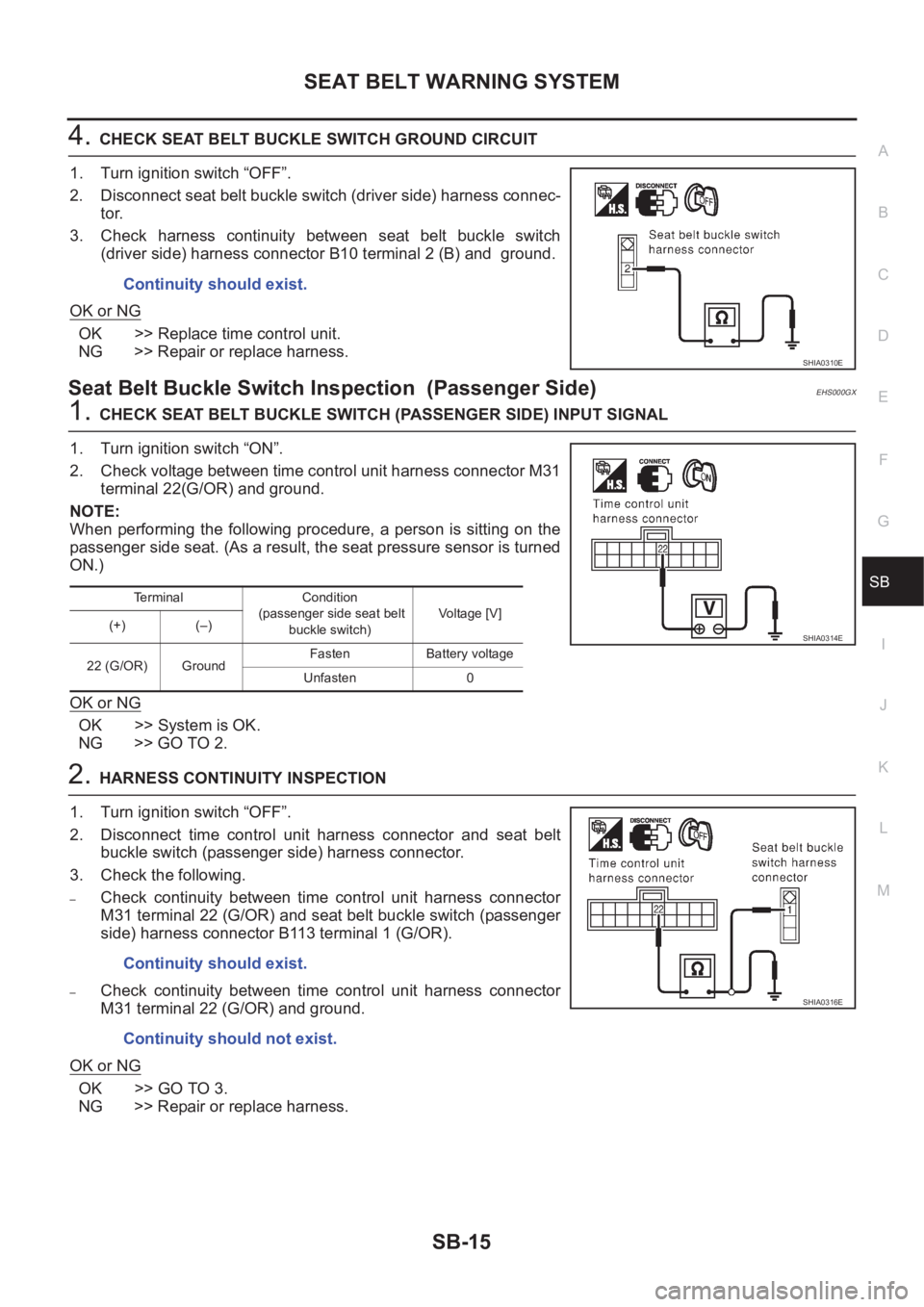
4.CHECK SEAT BELT BUCKLE SWITCH GROUND CIRCUIT
1. Turn ignition switch “OFF”.
2. Disconnect seat belt buckle switch (driver side) harness connec-
tor.
3. Check harness continuity between seat belt buckle switch
(driver side) harness connector B10 terminal 2 (B) and ground.
OK or NG
OK >> Replace time control unit.
NG >> Repair or replace harness.
Seat Belt Buckle Switch Inspection (Passenger Side)EHS000GX
1.CHECK SEAT BELT BUCKLE SWITCH (PASSENGER SIDE) INPUT SIGNAL
1. Turn ignition switch “ON”.
2. Check voltage between time control unit harness connector M31
terminal 22(G/OR) and ground.
NOTE:
When performing the following procedure, a person is sitting on the
passenger side seat. (As a result, the seat pressure sensor is turned
ON.)
OK or NG
OK >> System is OK.
NG >> GO TO 2.
2.HARNESS CONTINUITY INSPECTION
1. Turn ignition switch “OFF”.
2. Disconnect time control unit harness connector and seat belt
buckle switch (passenger side) harness connector.
3. Check the following.
–Check continuity between time control unit harness connector
M31 terminal 22 (G/OR) and seat belt buckle switch (passenger
side) harness connector B113 terminal 1 (G/OR).
–Check continuity between time control unit harness connector
M31 terminal 22 (G/OR) and ground.
OK or NG
OK >> GO TO 3.
NG >> Repair or replace harness. Continuity should exist.
SHIA0310E
Terminal Condition
(passenger side seat belt
buckle switch)Voltage [V]
(+) (–)
22 (G/OR) GroundFasten Battery voltage
Unfasten 0
SHIA0314E
Continuity should exist.
Continuity should not exist.
SHIA0316E
Page 3063 of 3833
POWER DOOR LOCK SYSTEM
BL-11
C
D
E
F
G
H
J
K
L
MA
B
BL
POWER DOOR LOCK SYSTEMPFP:24814
System DescriptionEIS001SE
OPERATION
Power door lock/unlock operation by door key cylinder
●With the key inserted into driver's door key cylinder, turning it to LOCK will lock all doors.
●With the key inserted into driver's door key cylinder, turning it to UNLOCK will unlock all doors.
Power door lock/unlock operation by lock/unlock switch
●With lock/unlock switch setting to LOCK will lock all doors.
●With lock/unlock switch setting to UNLOCK will unlock all doors.
Key reminder system
●If the ignition key is in the ignition key cylinder and driver door is open, setting lock/unlock switch, lock
knob, key or multi-remote controller to “LOCK” locks the door once but then immediately unlocks all doors.
(signal from door unlock sensor driver side)
Component Parts and Harness Connector LocationEIS004DC
PIIA0584E
Page 3078 of 3833

BL-26
POWER DOOR LOCK SYSTEM
Door Switch Check
EIS004DN
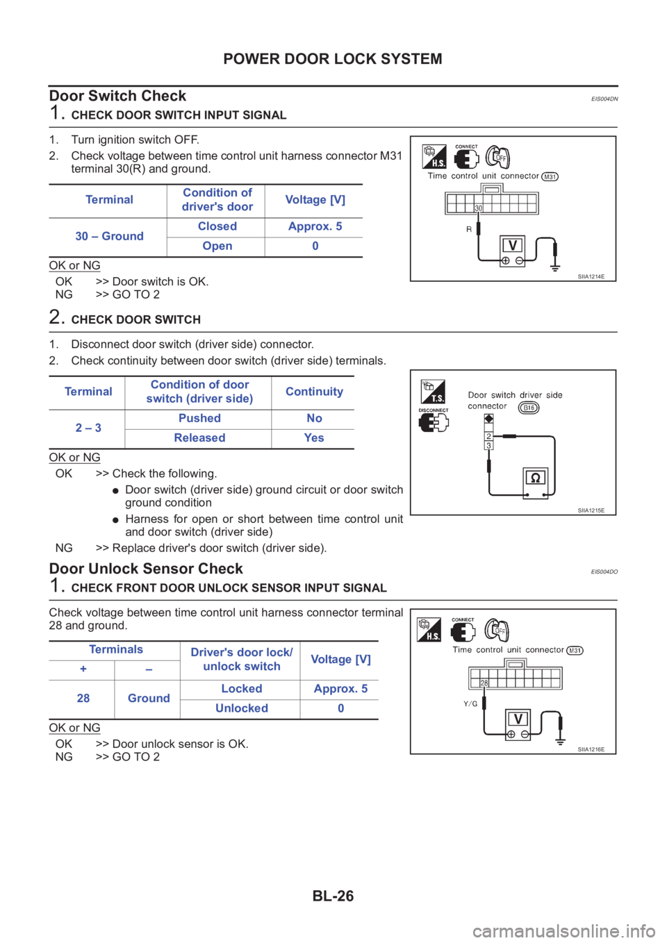
1. CHECK DOOR SWITCH INPUT SIGNAL
1. Turn ignition switch OFF.
2. Check voltage between time control unit harness connector M31
terminal 30(R) and ground.
OK or NG
OK >> Door switch is OK.
NG >> GO TO 2
2. CHECK DOOR SWITCH
1. Disconnect door switch (driver side) connector.
2. Check continuity between door switch (driver side) terminals.
OK or NG
OK >> Check the following.
●Door switch (driver side) ground circuit or door switch
ground condition
●Harness for open or short between time control unit
and door switch (driver side)
NG >> Replace driver's door switch (driver side).
Door Unlock Sensor CheckEIS004DO
1. CHECK FRONT DOOR UNLOCK SENSOR INPUT SIGNAL
Check voltage between time control unit harness connector terminal
28 and ground.
OK or NG
OK >> Door unlock sensor is OK.
NG >> GO TO 2Te r m i n a lCondition of
driver's doorVoltage [V]
30 – GroundClosed Approx. 5
Open 0
SIIA1214E
Te r m i n a lCondition of door
switch (driver side)Continuity
2 – 3Pushed No
Released Yes
SIIA1215E
Te r m i n a l s
Driver's door lock/
unlock switchVoltage [V]
+–
28 GroundLocked Approx. 5
Unlocked 0
SIIA1216E
Page 3081 of 3833

POWER DOOR LOCK — SUPER LOCK —
BL-29
C
D
E
F
G
H
J
K
L
MA
B
BL
POWER DOOR LOCK — SUPER LOCK —PFP:24814
System DescriptionEIS001R6
OUTLINE
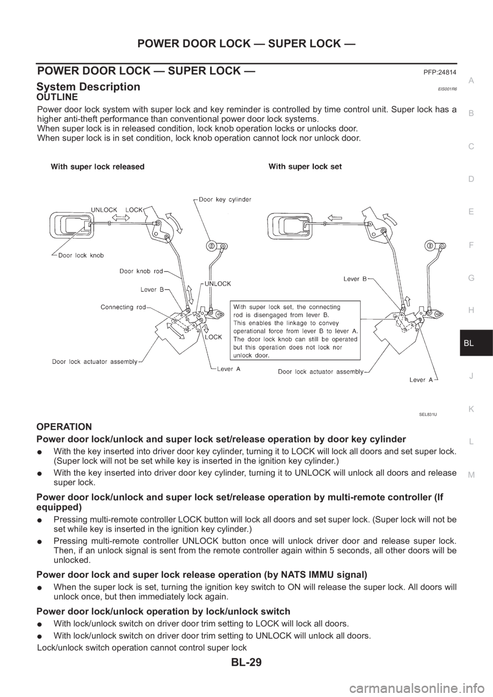
Power door lock system with super lock and key reminder is controlled by time control unit. Super lock has a
higher anti-theft performance than conventional power door lock systems.
When super lock is in released condition, lock knob operation locks or unlocks door.
When super lock is in set condition, lock knob operation cannot lock nor unlock door.
OPERATION
Power door lock/unlock and super lock set/release operation by door key cylinder
●With the key inserted into driver door key cylinder, turning it to LOCK will lock all doors and set super lock.
(Super lock will not be set while key is inserted in the ignition key cylinder.)
●With the key inserted into driver door key cylinder, turning it to UNLOCK will unlock all doors and release
super lock.
Power door lock/unlock and super lock set/release operation by multi-remote controller (If
equipped)
●Pressing multi-remote controller LOCK button will lock all doors and set super lock. (Super lock will not be
set while key is inserted in the ignition key cylinder.)
●Pressing multi-remote controller UNLOCK button once will unlock driver door and release super lock.
Then, if an unlock signal is sent from the remote controller again within 5 seconds, all other doors will be
unlocked.
Power door lock and super lock release operation (by NATS IMMU signal)
●When the super lock is set, turning the ignition key switch to ON will release the super lock. All doors will
unlock once, but then immediately lock again.
Power door lock/unlock operation by lock/unlock switch
●With lock/unlock switch on driver door trim setting to LOCK will lock all doors.
●With lock/unlock switch on driver door trim setting to UNLOCK will unlock all doors.
Lock/unlock switch operation cannot control super lock
SEL831U
Page 3082 of 3833
BL-30
POWER DOOR LOCK — SUPER LOCK —
Key reminder system
●If the ignition key is in the ignition key cylinder and driver door is open, setting lock/unlock switch, lock
knob, key or multi-remote controller to “LOCK” locks the door once but then immediately unlocks all doors.
(signal from door unlock sensor driver side)
System initialization
●System initialization is required when battery cables are reconnected. Conduct the following to release
super lock once;
– insert the key into the ignition key cylinder and turn it to ON.
– LOCK/UNLOCK operation using door key cylinder or multi-remote controller.
Page 3101 of 3833
POWER DOOR LOCK — SUPER LOCK —
BL-49
C
D
E
F
G
H
J
K
L
MA
B
BL
Door Switch CheckEIS004DY
1.CHECK DOOR SWITCH INPUT SIGNAL
1. Turn ignition switch OFF.
2. Check voltage between time control unit harness connector M31
terminal 30(R) and ground.
OK or NG
OK >> Door switch is OK.
NG >> GO TO 2
2.CHECK DOOR SWITCH
1. Disconnect door switch (driver side) connector.
2. Check continuity between door switch (driver side) terminals.
OK or NG
OK >> Check the following.
●Door switch (driver side) ground circuit or door switch
ground condition
●Harness for open or short between time control unit
and door switch (driver side)
NG >> Replace driver's door switch (driver side).Te r m i n a lCondition of
driver's doorVo l ta g e [ V ]
30 – GroundClosed Approx. 5
Open 0
SIIA1214E
Te r m i n a lCondition of door
switch (driver side)Continuity
2 – 3Pushed No
Released Yes
SIIA1215E
Page 3105 of 3833
POWER DOOR LOCK — SUPER LOCK —
BL-53
C
D
E
F
G
H
J
K
L
MA
B
BL
NATS Release Signal CheckEIS001SN
1.CHECK NATS SIGNAL CIRCUIT
1. Disconnect time control unit connector and NATS IMMU con-
nector.
2. Check continuity between time control unit terminal 34 and
NATS IMMU terminal 3.
3. Check continuity between time control unit terminal 34 and
ground.
OK or NG
OK >> GO TO 2
NG >> Repair harness.
2.CHECK NATS RELEASE SIGNAL
1. Connect time control unit connector and NATS IMMU connector.
2. Check voltage between time control unit terminal 34 and ground.
OK or NG
OK >> Replace time control unit.
NG >> Check NATS system.Continuity should exist.
Continuity should not exist.
SIIA1224E
Te r m i n a l
Condition of ignition switch Voltage [V]
+–
34 GroundOFF
Approx. 5
More than 17 seconds after
ignition switch is turned to ON
For 17 seconds after ignition
switch is turned to ONPulse
SIIA1225E