2001 NISSAN PICK-UP ECO mode
[x] Cancel search: ECO modePage 262 of 1306
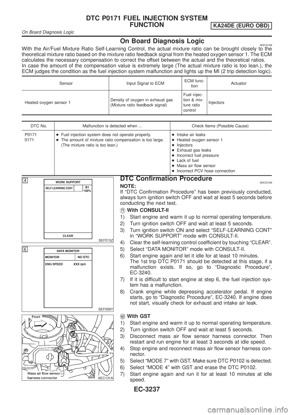
On Board Diagnosis LogicNEEC0188With the Air/Fuel Mixture Ratio Self-Learning Control, the actual mixture ratio can be brought closely to the
theoretical mixture ratio based on the mixture ratio feedback signal from the heated oxygen sensor 1. The ECM
calculates the necessary compensation to correct the offset between the actual and the theoretical ratios.
In case the amount of the compensation value is extremely large (The actual mixture ratio is too lean.), the
ECM judges the condition as the fuel injection system malfunction and lights up the MI (2 trip detection logic).
Sensor Input Signal to ECMECM func-
tionActuator
Heated oxygen sensor 1Density of oxygen in exhaust gas
(Mixture ratio feedback signal)Fuel injec-
tion & mix-
ture ratio
controlInjectors
DTC No. Malfunction is detected when ... Check Items (Possible Cause)
P0171
0171+Fuel injection system does not operate properly.
+The amount of mixture ratio compensation is too large.
(The mixture ratio is too lean.)+Intake air leaks
+Heated oxygen sensor 1
+Injectors
+Exhaust gas leaks
+Incorrect fuel pressure
+Lack of fuel
+Mass air flow sensor
+Incorrect PCV hose connection
SEF215Z
SEF058Y
DTC Confirmation ProcedureNEEC0189NOTE:
If ªDTC Confirmation Procedureº has been previously conducted,
always turn ignition switch OFF and wait at least 5 seconds before
conducting the next test.
With CONSULT-II
1) Start engine and warm it up to normal operating temperature.
2) Turn ignition switch OFF and wait at least 5 seconds.
3) Turn ignition switch ON and select ªSELF-LEARNING CONTº
in ªWORK SUPPORTº mode with CONSULT-II.
4) Clear the self-learning control coefficient by touching ªCLEARº.
5) Select ªDATA MONITORº mode with CONSULT-II.
6) Start engine again and let it idle for at least 10 minutes.
The 1st trip DTC P0171 should be detected at this stage, if a
malfunction exists. If so, go to ªDiagnostic Procedureº,
EC-3240.
7) If it is difficult to start engine at step 6, the fuel injection sys-
tem has a malfunction.
8) Crank engine while depressing accelerator pedal. If engine
starts, go to ªDiagnostic Procedureº, EC-3240. If engine does
not start, visually check for exhaust and intake air leak.
AEC131A
With GST
1) Start engine and warm it up to normal operating temperature.
2) Turn ignition switch OFF and wait at least 5 seconds.
3) Disconnect mass air flow sensor harness connector. Then
restart and run engine for at least 3 seconds at idle speed.
4) Stop engine and reconnect mass air flow sensor harness con-
nector.
5) Select ªMODE 7º with GST. Make sure DTC P0102 is detected.
6) Select ªMODE 4º with GST and erase the DTC P0102.
7) Start engine again and run it for at least 10 minutes at idle
speed.
DTC P0171 FUEL INJECTION SYSTEM
FUNCTION
KA24DE (EURO OBD)
On Board Diagnosis Logic
EC-3237
Page 269 of 1306
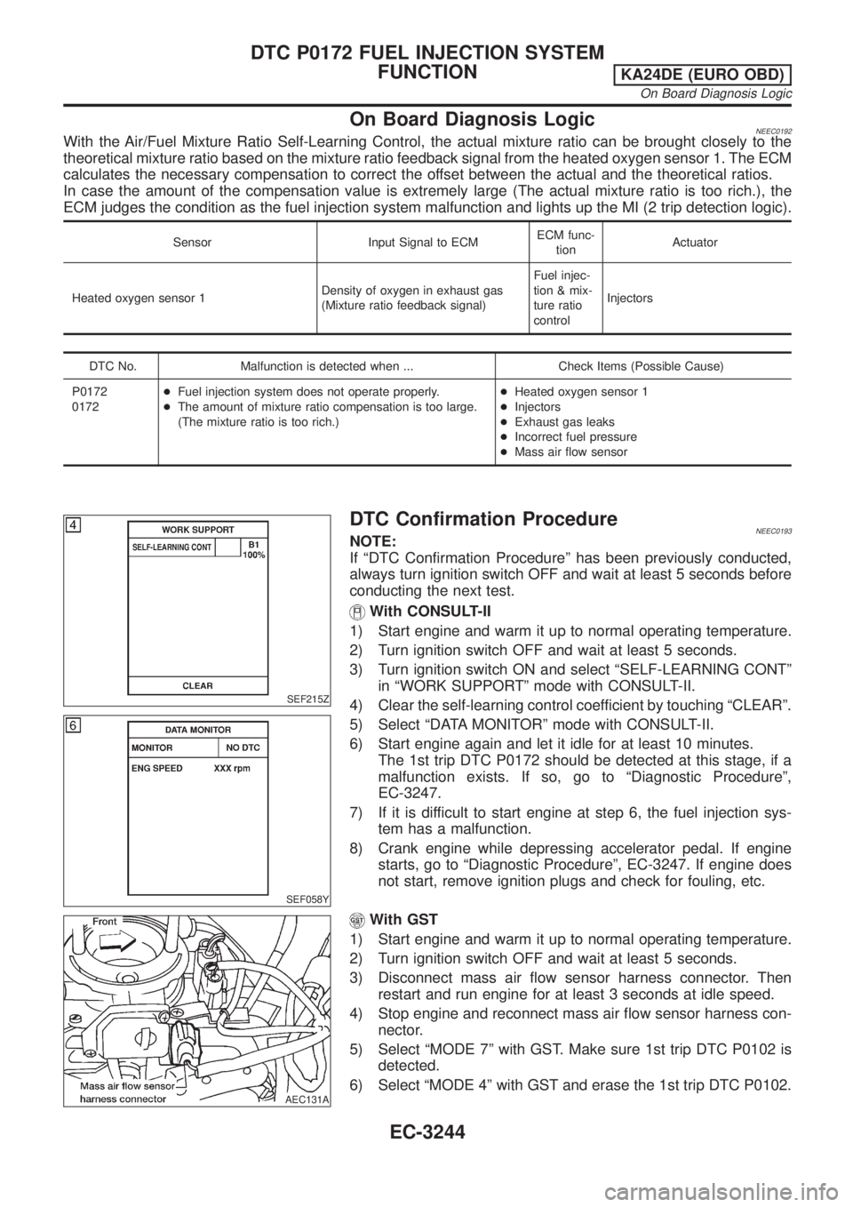
On Board Diagnosis LogicNEEC0192With the Air/Fuel Mixture Ratio Self-Learning Control, the actual mixture ratio can be brought closely to the
theoretical mixture ratio based on the mixture ratio feedback signal from the heated oxygen sensor 1. The ECM
calculates the necessary compensation to correct the offset between the actual and the theoretical ratios.
In case the amount of the compensation value is extremely large (The actual mixture ratio is too rich.), the
ECM judges the condition as the fuel injection system malfunction and lights up the MI (2 trip detection logic).
Sensor Input Signal to ECMECM func-
tionActuator
Heated oxygen sensor 1Density of oxygen in exhaust gas
(Mixture ratio feedback signal)Fuel injec-
tion & mix-
ture ratio
controlInjectors
DTC No. Malfunction is detected when ... Check Items (Possible Cause)
P0172
0172+Fuel injection system does not operate properly.
+The amount of mixture ratio compensation is too large.
(The mixture ratio is too rich.)+Heated oxygen sensor 1
+Injectors
+Exhaust gas leaks
+Incorrect fuel pressure
+Mass air flow sensor
SEF215Z
SEF058Y
DTC Confirmation ProcedureNEEC0193NOTE:
If ªDTC Confirmation Procedureº has been previously conducted,
always turn ignition switch OFF and wait at least 5 seconds before
conducting the next test.
With CONSULT-II
1) Start engine and warm it up to normal operating temperature.
2) Turn ignition switch OFF and wait at least 5 seconds.
3) Turn ignition switch ON and select ªSELF-LEARNING CONTº
in ªWORK SUPPORTº mode with CONSULT-II.
4) Clear the self-learning control coefficient by touching ªCLEARº.
5) Select ªDATA MONITORº mode with CONSULT-II.
6) Start engine again and let it idle for at least 10 minutes.
The 1st trip DTC P0172 should be detected at this stage, if a
malfunction exists. If so, go to ªDiagnostic Procedureº,
EC-3247.
7) If it is difficult to start engine at step 6, the fuel injection sys-
tem has a malfunction.
8) Crank engine while depressing accelerator pedal. If engine
starts, go to ªDiagnostic Procedureº, EC-3247. If engine does
not start, remove ignition plugs and check for fouling, etc.
AEC131A
With GST
1) Start engine and warm it up to normal operating temperature.
2) Turn ignition switch OFF and wait at least 5 seconds.
3) Disconnect mass air flow sensor harness connector. Then
restart and run engine for at least 3 seconds at idle speed.
4) Stop engine and reconnect mass air flow sensor harness con-
nector.
5) Select ªMODE 7º with GST. Make sure 1st trip DTC P0102 is
detected.
6) Select ªMODE 4º with GST and erase the 1st trip DTC P0102.
DTC P0172 FUEL INJECTION SYSTEM
FUNCTION
KA24DE (EURO OBD)
On Board Diagnosis Logic
EC-3244
Page 274 of 1306
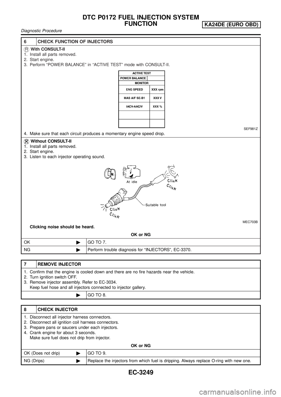
6 CHECK FUNCTION OF INJECTORS
With CONSULT-II
1. Install all parts removed.
2. Start engine.
3. Perform ªPOWER BALANCEº in ªACTIVE TESTº mode with CONSULT-II.
SEF981Z
4. Make sure that each circuit produces a momentary engine speed drop.
Without CONSULT-II
1. Install all parts removed.
2. Start engine.
3. Listen to each injector operating sound.
MEC703B
Clicking noise should be heard.
OK or NG
OK©GO TO 7.
NG©Perform trouble diagnosis for ªINJECTORSº, EC-3370.
7 REMOVE INJECTOR
1. Confirm that the engine is cooled down and there are no fire hazards near the vehicle.
2. Turn ignition switch OFF.
3. Remove injector assembly. Refer to EC-3034.
Keep fuel hose and all injectors connected to injector gallery.
©GO TO 8.
8 CHECK INJECTOR
1. Disconnect all injector harness connectors.
2. Disconnect all ignition coil harness connectors.
3. Prepare pans or saucers under each injectors.
4. Crank engine for about 3 seconds.
Make sure fuel does not drip from injector.
OK or NG
OK (Does not drip)©GO TO 9.
NG (Drips)©Replace the injectors from which fuel is dripping. Always replace O-ring with new one.
DTC P0172 FUEL INJECTION SYSTEM
FUNCTION
KA24DE (EURO OBD)
Diagnostic Procedure
EC-3249
Page 276 of 1306
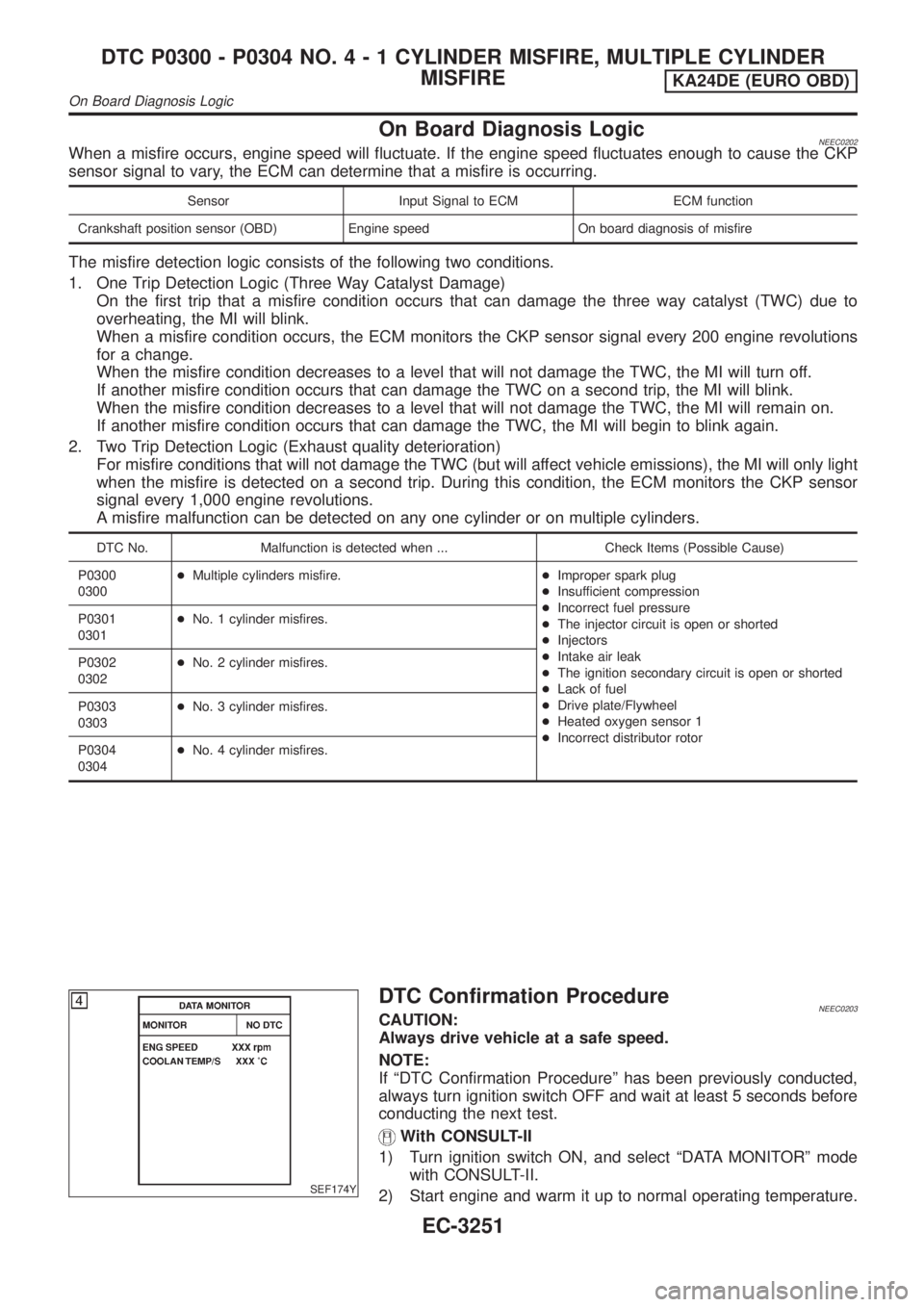
On Board Diagnosis LogicNEEC0202When a misfire occurs, engine speed will fluctuate. If the engine speed fluctuates enough to cause the CKP
sensor signal to vary, the ECM can determine that a misfire is occurring.
Sensor Input Signal to ECM ECM function
Crankshaft position sensor (OBD) Engine speed On board diagnosis of misfire
The misfire detection logic consists of the following two conditions.
1. One Trip Detection Logic (Three Way Catalyst Damage)
On the first trip that a misfire condition occurs that can damage the three way catalyst (TWC) due to
overheating, the MI will blink.
When a misfire condition occurs, the ECM monitors the CKP sensor signal every 200 engine revolutions
for a change.
When the misfire condition decreases to a level that will not damage the TWC, the MI will turn off.
If another misfire condition occurs that can damage the TWC on a second trip, the MI will blink.
When the misfire condition decreases to a level that will not damage the TWC, the MI will remain on.
If another misfire condition occurs that can damage the TWC, the MI will begin to blink again.
2. Two Trip Detection Logic (Exhaust quality deterioration)
For misfire conditions that will not damage the TWC (but will affect vehicle emissions), the MI will only light
when the misfire is detected on a second trip. During this condition, the ECM monitors the CKP sensor
signal every 1,000 engine revolutions.
A misfire malfunction can be detected on any one cylinder or on multiple cylinders.
DTC No. Malfunction is detected when ... Check Items (Possible Cause)
P0300
0300+Multiple cylinders misfire.+Improper spark plug
+Insufficient compression
+Incorrect fuel pressure
+The injector circuit is open or shorted
+Injectors
+Intake air leak
+The ignition secondary circuit is open or shorted
+Lack of fuel
+Drive plate/Flywheel
+Heated oxygen sensor 1
+Incorrect distributor rotor P0301
0301+No. 1 cylinder misfires.
P0302
0302+No. 2 cylinder misfires.
P0303
0303+No. 3 cylinder misfires.
P0304
0304+No. 4 cylinder misfires.
SEF174Y
DTC Confirmation ProcedureNEEC0203CAUTION:
Always drive vehicle at a safe speed.
NOTE:
If ªDTC Confirmation Procedureº has been previously conducted,
always turn ignition switch OFF and wait at least 5 seconds before
conducting the next test.
With CONSULT-II
1) Turn ignition switch ON, and select ªDATA MONITORº mode
with CONSULT-II.
2) Start engine and warm it up to normal operating temperature.
DTC P0300 - P0304 NO.4-1CYLINDER MISFIRE, MULTIPLE CYLINDER
MISFIRE
KA24DE (EURO OBD)
On Board Diagnosis Logic
EC-3251
Page 282 of 1306
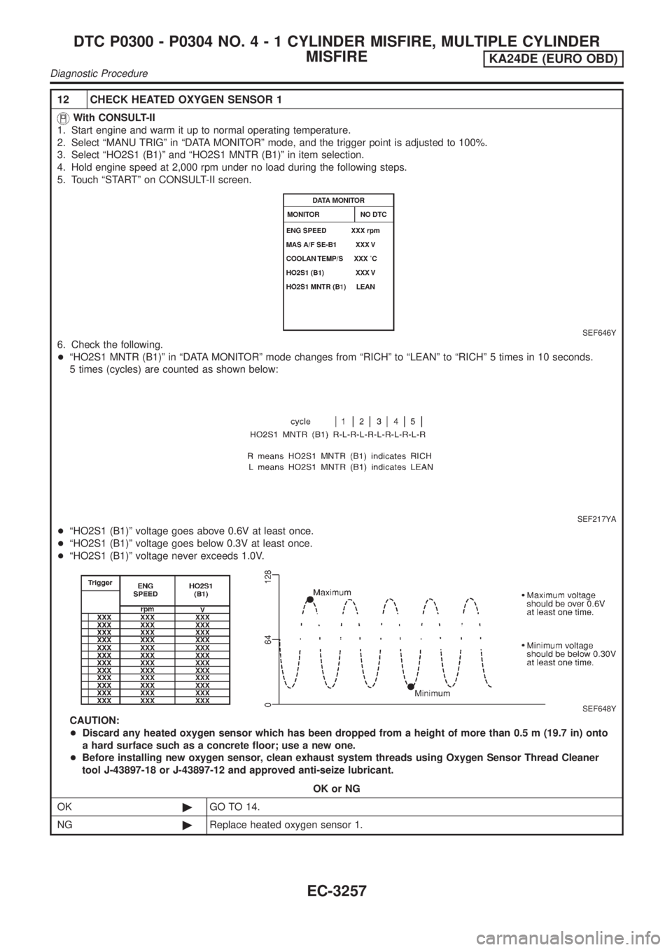
12 CHECK HEATED OXYGEN SENSOR 1
With CONSULT-II
1. Start engine and warm it up to normal operating temperature.
2. Select ªMANU TRIGº in ªDATA MONITORº mode, and the trigger point is adjusted to 100%.
3. Select ªHO2S1 (B1)º and ªHO2S1 MNTR (B1)º in item selection.
4. Hold engine speed at 2,000 rpm under no load during the following steps.
5. Touch ªSTARTº on CONSULT-II screen.
SEF646Y
6. Check the following.
+ªHO2S1 MNTR (B1)º in ªDATA MONITORº mode changes from ªRICHº to ªLEANº to ªRICHº 5 times in 10 seconds.
5 times (cycles) are counted as shown below:
SEF217YA
+ªHO2S1 (B1)º voltage goes above 0.6V at least once.
+ªHO2S1 (B1)º voltage goes below 0.3V at least once.
+ªHO2S1 (B1)º voltage never exceeds 1.0V.
SEF648Y
CAUTION:
+Discard any heated oxygen sensor which has been dropped from a height of more than 0.5 m (19.7 in) onto
a hard surface such as a concrete floor; use a new one.
+Before installing new oxygen sensor, clean exhaust system threads using Oxygen Sensor Thread Cleaner
tool J-43897-18 or J-43897-12 and approved anti-seize lubricant.
OK or NG
OK©GO TO 14.
NG©Replace heated oxygen sensor 1.
DTC P0300 - P0304 NO.4-1CYLINDER MISFIRE, MULTIPLE CYLINDER
MISFIRE
KA24DE (EURO OBD)
Diagnostic Procedure
EC-3257
Page 283 of 1306
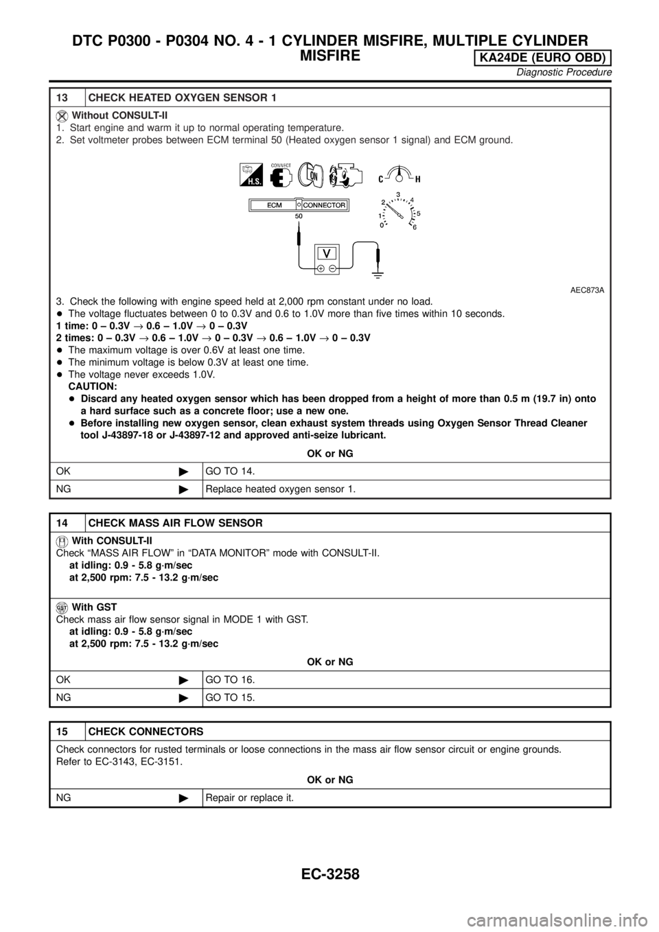
13 CHECK HEATED OXYGEN SENSOR 1
Without CONSULT-II
1. Start engine and warm it up to normal operating temperature.
2. Set voltmeter probes between ECM terminal 50 (Heated oxygen sensor 1 signal) and ECM ground.
AEC873A
3. Check the following with engine speed held at 2,000 rpm constant under no load.
+The voltage fluctuates between 0 to 0.3V and 0.6 to 1.0V more than five times within 10 seconds.
1 time: 0 ± 0.3V®0.6 ± 1.0V®0 ± 0.3V
2 times: 0 ± 0.3V®0.6 ± 1.0V®0 ± 0.3V®0.6 ± 1.0V®0 ± 0.3V
+The maximum voltage is over 0.6V at least one time.
+The minimum voltage is below 0.3V at least one time.
+The voltage never exceeds 1.0V.
CAUTION:
+Discard any heated oxygen sensor which has been dropped from a height of more than 0.5 m (19.7 in) onto
a hard surface such as a concrete floor; use a new one.
+Before installing new oxygen sensor, clean exhaust system threads using Oxygen Sensor Thread Cleaner
tool J-43897-18 or J-43897-12 and approved anti-seize lubricant.
OK or NG
OK©GO TO 14.
NG©Replace heated oxygen sensor 1.
14 CHECK MASS AIR FLOW SENSOR
With CONSULT-II
Check ªMASS AIR FLOWº in ªDATA MONITORº mode with CONSULT-II.
at idling: 0.9 - 5.8 g´m/sec
at 2,500 rpm: 7.5 - 13.2 g´m/sec
With GST
Check mass air flow sensor signal in MODE 1 with GST.
at idling: 0.9 - 5.8 g´m/sec
at 2,500 rpm: 7.5 - 13.2 g´m/sec
OK or NG
OK©GO TO 16.
NG©GO TO 15.
15 CHECK CONNECTORS
Check connectors for rusted terminals or loose connections in the mass air flow sensor circuit or engine grounds.
Refer to EC-3143, EC-3151.
OK or NG
NG©Repair or replace it.
DTC P0300 - P0304 NO.4-1CYLINDER MISFIRE, MULTIPLE CYLINDER
MISFIRE
KA24DE (EURO OBD)
Diagnostic Procedure
EC-3258
Page 285 of 1306
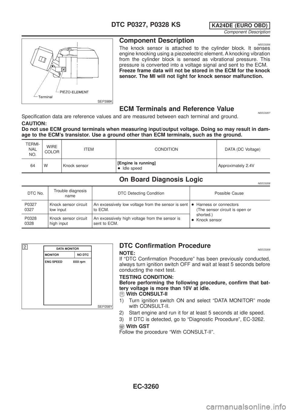
SEF598K
Component DescriptionNEEC0206The knock sensor is attached to the cylinder block. It senses
engine knocking using a piezoelectric element. A knocking vibration
from the cylinder block is sensed as vibrational pressure. This
pressure is converted into a voltage signal and sent to the ECM.
Freeze frame data will not be stored in the ECM for the knock
sensor. The MI will not light for knock sensor malfunction.
ECM Terminals and Reference ValueNEEC0207Specification data are reference values and are measured between each terminal and ground.
CAUTION:
Do not use ECM ground terminals when measuring input/output voltage. Doing so may result in dam-
age to the ECM's transistor. Use a ground other than ECM terminals, such as the ground.
TERMI-
NAL
NO.WIRE
COLORITEM CONDITION DATA (DC Voltage)
64 W Knock sensor[Engine is running]
+Idle speedApproximately 2.4V
On Board Diagnosis LogicNEEC0208
DTC No.Trouble diagnosis
nameDTC Detecting Condition Possible Cause
P0327
0327Knock sensor circuit
low inputAn excessively low voltage from the sensor is sent
to ECM.+Harness or connectors
(The sensor circuit is open or
shorted.)
+Knock sensor P0328
0328Knock sensor circuit
high inputAn excessively high voltage from the sensor is
sent to ECM.
SEF058Y
DTC Confirmation ProcedureNEEC0209NOTE:
If ªDTC Confirmation Procedureº has been previously conducted,
always turn ignition switch OFF and wait at least 5 seconds before
conducting the next test.
TESTING CONDITION:
Before performing the following procedure, confirm that bat-
tery voltage is more than 10V at idle.
With CONSULT-II
1) Turn ignition switch ON and select ªDATA MONITORº mode
with CONSULT-II.
2) Start engine and run it for at least 5 seconds at idle speed.
3) If DTC is detected, go to ªDiagnostic Procedureº, EC-3262.
With GST
Follow the procedure ªWith CONSULT-IIº.
DTC P0327, P0328 KSKA24DE (EURO OBD)
Component Description
EC-3260
Page 290 of 1306

SEF058Y
DTC Confirmation ProcedureNEEC0216NOTE:
If ªDTC Confirmation Procedureº has been previously conducted,
always turn ignition switch OFF and wait at least 5 seconds before
conducting the next test.
With CONSULT-II
1) Turn ignition switch ON and select ªDATA MONITORº mode
with CONSULT-II.
2) Start engine and run it for at least 15 seconds at idle speed.
3) If 1st trip DTC is detected, go to ªDiagnostic Procedureº,
EC-3267.
With GST
Follow the procedure ªWith CONSULT-IIº.
DTC P0335 CKP SENSOR (OBD)KA24DE (EURO OBD)
DTC Confirmation Procedure
EC-3265