Page 386 of 1306
SEF928V
Component DescriptionNEEC0319IGNITION COIL & POWER TRANSISTORNEEC0319S01The ignition signal from the ECM is sent to the power transistor.
The power transistor switches the ignition coil primary circuit on
and off. As the primary circuit is turned on and off, the proper high
voltage is induced in the coil secondary circuit.
The distributor is not repairable and must be replaced as an
assembly except distributor cap and rotor head.
NOTE:
The rotor screw which secures the distributor rotor head to the
distributor shaft must be tightened properly.
: 3.3 - 3.9 N´m (0.34 - 0.40 kg-m, 29.5 - 34.7 in-lb)
CONSULT-II Reference Value in Data Monitor
Mode
NEEC0320
MONITOR ITEM CONDITION SPECIFICATION
IGN TIMING+Engine: After warming up
+Air conditioner switch: OFF
+Shift lever: ªNº
+No-loadIdle Approx. 15É BTDC
2,000 rpm More than 30É BTDC
IGNITION SIGNALKA24DE (EURO OBD)
Component Description
EC-3361
Page 403 of 1306

System DescriptionNEEC0444
Sensor Input Signal to ECMECM func-
tionActuator
Camshaft position sensor Engine speed
Fuel pump
controlFuel pump relay
Ignition switch Start signal
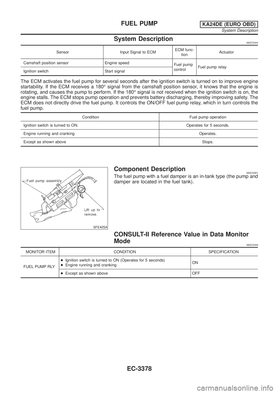
The ECM activates the fuel pump for several seconds after the ignition switch is turned on to improve engine
startability. If the ECM receives a 180É signal from the camshaft position sensor, it knows that the engine is
rotating, and causes the pump to perform. If the 180É signal is not received when the ignition switch is on, the
engine stalls. The ECM stops pump operation and prevents battery discharging, thereby improving safety. The
ECM does not directly drive the fuel pump. It controls the ON/OFF fuel pump relay, which in turn controls the
fuel pump.
Condition Fuel pump operation
Ignition switch is turned to ON. Operates for 5 seconds.
Engine running and cranking Operates.
Except as shown aboveStops.
SFE425A
Component DescriptionNEEC0501The fuel pump with a fuel damper is an in-tank type (the pump and
damper are located in the fuel tank).
CONSULT-II Reference Value in Data Monitor
Mode
NEEC0445
MONITOR ITEM CONDITION SPECIFICATION
FUEL PUMP RLY+Ignition switch is turned to ON (Operates for 5 seconds)
+Engine running and crankingON
+Except as shown above OFF
FUEL PUMPKA24DE (EURO OBD)
System Description
EC-3378
Page 404 of 1306
ECM Terminals and Reference Value=NEEC0446Specification data are reference values and are measured between each terminal and ground.
CAUTION:
Do not use ECM ground terminals when measuring input/output voltage. Doing so may result in dam-
age to the ECM's transistor. Use a ground other than ECM terminals, such as the ground.
TERMI-
NAL
NO.WIRE
COLORITEM CONDITION DATA (DC Voltage)
11*1 Y Fuel pump relay[Ignition switch ªONº]
+For 5 seconds after turning ignition switch ªONº
[Engine is running]0-1V
[Ignition switch ªONº]
+More than 5 seconds after turning ignition switch
ªONºBATTERY VOLTAGE
(11 - 14V)
14*2 Y Fuel pump relay[Ignition switch ON]
+For 5 seconds after turning ignition switch0-1V
[Ignition switch ON]
+More than 5 seconds after turning ignition switch
ONBATTERY VOLTAGE
(11 - 14V)
*1: Model without NATS (Nissan Anti-Theft System)
*2: Model with NATS (Nissan Anti-Theft System)
FUEL PUMPKA24DE (EURO OBD)
ECM Terminals and Reference Value
EC-3379
Page 408 of 1306
7 CHECK FUEL PUMP RELAY
With CONSULT-II
1. Reconnect fuel pump relay, fuel level sensor unit and fuel pump harness connector and ECM harness connector.
2. Turn ignition switch ON.
3. Turn fuel pump relay ªONº and ªOFFº in ªACTIVE TESTº mode with CONSULT-II and check operating sound.
SEF724Z
Without CONSULT-II
Check continuity between terminals 3 and 5.
PBIB0098E
MTBL0306
OK or NG
OK©GO TO 8.
NG©Replace fuel pump relay.
FUEL PUMPKA24DE (EURO OBD)
Diagnostic Procedure
EC-3383
Page 423 of 1306

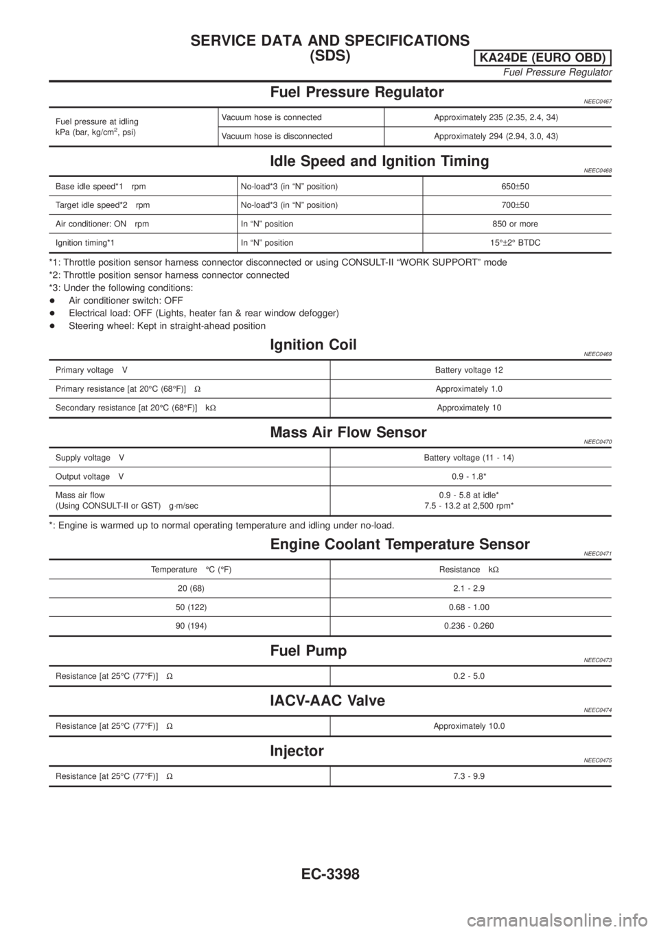
Fuel Pressure RegulatorNEEC0467
Fuel pressure at idling
kPa (bar, kg/cm2, psi)Vacuum hose is connected Approximately 235 (2.35, 2.4, 34)
Vacuum hose is disconnected Approximately 294 (2.94, 3.0, 43)
Idle Speed and Ignition TimingNEEC0468
Base idle speed*1 rpm No-load*3 (in ªNº position) 650±50
Target idle speed*2 rpm No-load*3 (in ªNº position) 700±50
Air conditioner: ON rpm In ªNº position 850 or more
Ignition timing*1 In ªNº position 15ɱ2É BTDC
*1: Throttle position sensor harness connector disconnected or using CONSULT-II ªWORK SUPPORTº mode
*2: Throttle position sensor harness connector connected
*3: Under the following conditions:
+Air conditioner switch: OFF
+Electrical load: OFF (Lights, heater fan & rear window defogger)
+Steering wheel: Kept in straight-ahead position
Ignition CoilNEEC0469
Primary voltage VBattery voltage 12
Primary resistance [at 20ÉC (68ÉF)]WApproximately 1.0
Secondary resistance [at 20ÉC (68ÉF)] kWApproximately 10
Mass Air Flow SensorNEEC0470
Supply voltage VBattery voltage (11 - 14)
Output voltage V0.9 - 1.8*
Mass air flow
(Using CONSULT-II or GST) g´m/sec0.9 - 5.8 at idle*
7.5 - 13.2 at 2,500 rpm*
*: Engine is warmed up to normal operating temperature and idling under no-load.
Engine Coolant Temperature SensorNEEC0471
Temperature ÉC (ÉF) Resistance kW
20 (68) 2.1 - 2.9
50 (122) 0.68 - 1.00
90 (194) 0.236 - 0.260
Fuel PumpNEEC0473
Resistance [at 25ÉC (77ÉF)]W0.2 - 5.0
IACV-AAC ValveNEEC0474
Resistance [at 25ÉC (77ÉF)]WApproximately 10.0
InjectorNEEC0475
Resistance [at 25ÉC (77ÉF)]W7.3 - 9.9
SERVICE DATA AND SPECIFICATIONS
(SDS)
KA24DE (EURO OBD)
Fuel Pressure Regulator
EC-3398
Page 453 of 1306

DTC and MIL Detection Logic
When a malfunction is detected, the malfunction (DTC) is stored in the ECM memory.
The MIL will light up each time the ECM detects malfunction. For diagnostic items causing the MIL to light
up, refer to ªTROUBLE DIAGNOSIS Ð INDEXº, EC-3400.
Diagnostic Trouble Code (DTC)
HOW TO READ DTC
The DTC can be read by the following methods.
Without CONSULT-II
ECM displays the DTC by a set of four digit numbers with MIL illumination in the diagnostic test mode II
(Self-diagnostic results). Example: 0407, 1004, etc.
With CONSULT-II
CONSULT-II displays the DTC in ªSELF-DIAG RESULTSº mode. Examples: ªCRANK POS SEN (TDC)º, etc.
HOW TO ERASE DTC
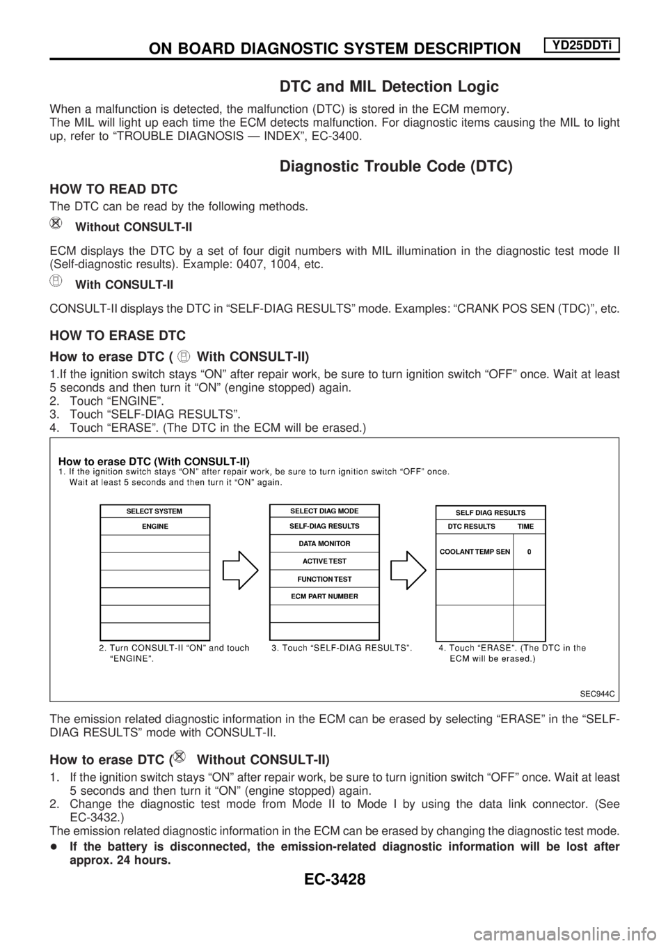
How to erase DTC (
With CONSULT-II)
1.If the ignition switch stays ªONº after repair work, be sure to turn ignition switch ªOFFº once. Wait at least
5 seconds and then turn it ªONº (engine stopped) again.
2. Touch ªENGINEº.
3. Touch ªSELF-DIAG RESULTSº.
4. Touch ªERASEº. (The DTC in the ECM will be erased.)
The emission related diagnostic information in the ECM can be erased by selecting ªERASEº in the ªSELF-
DIAG RESULTSº mode with CONSULT-II.
How to erase DTC (Without CONSULT-II)
1. If the ignition switch stays ªONº after repair work, be sure to turn ignition switch ªOFFº once. Wait at least
5 seconds and then turn it ªONº (engine stopped) again.
2. Change the diagnostic test mode from Mode II to Mode I by using the data link connector. (See
EC-3432.)
The emission related diagnostic information in the ECM can be erased by changing the diagnostic test mode.
+If the battery is disconnected, the emission-related diagnostic information will be lost after
approx. 24 hours.
SEC944C
ON BOARD DIAGNOSTIC SYSTEM DESCRIPTIONYD25DDTi
EC-3428
Page 457 of 1306

Diagnostic test mode I Ð Bulb check
In this mode, the MIL on the instrument panel should stay ON. If it remains OFF, check the bulb. Refer to
EL section, ªWARNING LAMPS AND CHIMEº or see EC-3647.
Diagnostic test mode I Ð Malfunction warning
MIL Condition
ON When the malfunction is detected or the ECM's CPU is malfunctioning.
OFF No malfunction.
Diagnostic test mode II Ð Self-diagnostic results
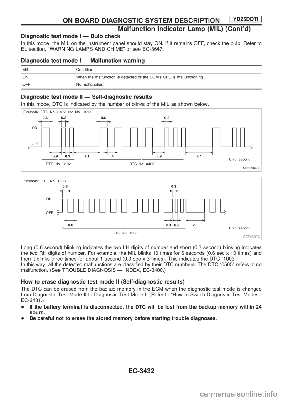
In this mode, DTC is indicated by the number of blinks of the MIL as shown below.
Long (0.6 second) blinking indicates the two LH digits of number and short (0.3 second) blinking indicates
the two RH digits of number. For example, the MIL blinks 10 times for 6 seconds (0.6 sec x 10 times) and
then it blinks three times for about 1 second (0.3 sec x 3 times). This indicates the DTC ª1003º.
In this way, all the detected malfunctions are classified by their DTC numbers. The DTC ª0505º refers to no
malfunction. (See TROUBLE DIAGNOSIS Ð INDEX, EC-3400.)
How to erase diagnostic test mode II (Self-diagnostic results)
The DTC can be erased from the backup memory in the ECM when the diagnostic test mode is changed
from Diagnostic Test Mode II to Diagnostic Test Mode I. (Refer to ªHow to Switch Diagnostic Test Modesº,
EC-3431.)
+If the battery terminal is disconnected, the DTC will be lost from the backup memory within 24
hours.
+Be careful not to erase the stored memory before starting trouble diagnoses.
SEF298QA
SEF162PB
ON BOARD DIAGNOSTIC SYSTEM DESCRIPTIONYD25DDTi
Malfunction Indicator Lamp (MIL) (Cont'd)
EC-3432
Page 462 of 1306
![NISSAN PICK-UP 2001 Repair Manual Monitored item
[Unit]ECM
input
signalsMain
signalsDescription Remarks
EGR VOL CON/V
[step]
j+Indicates the EGR volume control value
computed by the ECM according to the
input signals.
+The opening bec NISSAN PICK-UP 2001 Repair Manual Monitored item
[Unit]ECM
input
signalsMain
signalsDescription Remarks
EGR VOL CON/V
[step]
j+Indicates the EGR volume control value
computed by the ECM according to the
input signals.
+The opening bec](/manual-img/5/57372/w960_57372-461.png)
Monitored item
[Unit]ECM
input
signalsMain
signalsDescription Remarks
EGR VOL CON/V
[step]
j+Indicates the EGR volume control value
computed by the ECM according to the
input signals.
+The opening becomes larger as the
value increases.
BARO SEN [kPa]
j+The barometric pressure (determined by
the signal voltage from the barometric
pressure sensor built into the ECM) is
displayed.
NOTE:
Any monitored item that does not match the vehicle being diagnosed is deleted from the display automatically.
ACTIVE TEST MODE
TEST ITEM CONDITION JUDGEMENT CHECK ITEM (REMEDY)
COOLING FAN+Ignition switch: ON
+Turn cooling fan ªONº and ªOFFº
using CONSULT-II.Cooling fan moves and stops.+Harness and connector
+Cooling fan motor
+Cooling fan relay
OFF ACCEL PO
SIG+Clears the self-learning fully closed accelerator position, detected by accelerator position sensor, from the
ECM.
GLOW RLY+Ignition switch: ON (Engine
stopped)
+Turn the glow relay ªONº and
ªOFFº using CONSULT-II and
listen to operating sound.Glow relay makes the operating
sound.+Harness and connector
+Glow relay
INJ TIMING*1+Engine: Return to the original
trouble condition
+Retard the injection timing using
CONSULT-II.If trouble symptom disappears, see
CHECK ITEM.+Electronic control fuel injection
pump
EGR VOL CONT/V+Ignition switch: ON
+Change EGR volume control
valve opening step using CON-
SULT-II.EGR volume control valve makes
an operating sound.+Harness and connector
+EGR volume control valve
*1: When using this item, DTC 0707 ªP7zF/INJ TIMG FBº may be detected. If so, erase it because it is not a malfunction.
ON BOARD DIAGNOSTIC SYSTEM DESCRIPTIONYD25DDTi
CONSULT-II (Cont'd)
EC-3437